REAR DOOR SUNSHADE SYSTEM Only Front Switch cannot Operate Right and Left Door Sunshade
DESCRIPTION
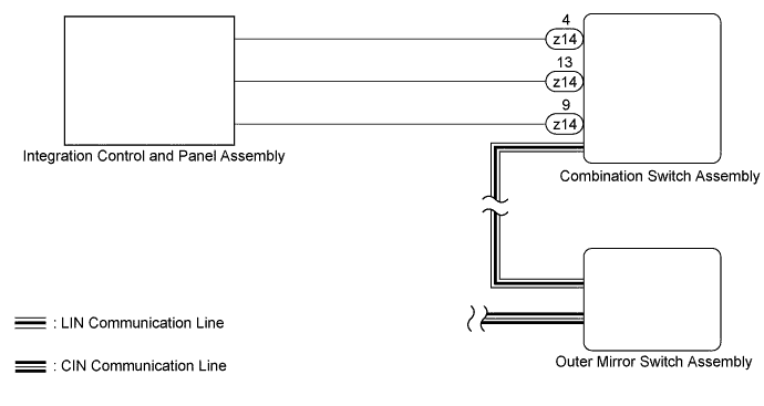
A rear door sunshade switch signal is sent from the integration control and panel assembly to the combination switch assembly. Then the signal is sent through LIN communication to the outer mirror switch assembly, which then sends the signal through CAN communication to the rear door ECUs, and the rear door sunshade operates.
WIRING DIAGRAM
INSPECTION PROCEDURE
PROCEDURE
-
CHECK DTC
-
Clear the DTC Click here.
-
Check the DTC Click here.
Result Result Proceed to No DTCs are output A U1114 is output (for LHD) B U1114 is output (for RHD) C U1127 is output D
B 
GO TO CAN COMMUNICATION SYSTEM Click here
C
GO TO CAN COMMUNICATION SYSTEM Click here
D
GO TO LIN COMMUNICATION SYSTEM Click here
A 
-
-
INSPECT INTEGRATION CONTROL AND PANEL ASSEMBLY
-
Remove the integration control and panel assembly Click here.
-
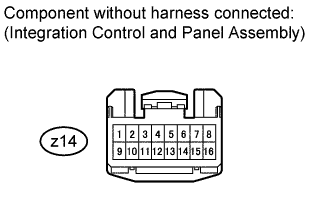
Measure the resistance according to the value(s) in the table below.
Standard resistance Tester Connection Switch Condition Specified Condition z14-4 - z14-9 Rear door sunshade switch RH is pushed Below 200 Ω z14-4 - z14-9 Rear door sunshade switch RH is not pushed 10 kΩ or higher z14-13 - z14-9 Rear door sunshade switch LH is pushed Below 200 Ω z14-13 - z14-9 Rear door sunshade switch LH is not pushed 10 kΩ or higher
NG
REPLACE INTEGRATION CONTROL AND PANEL ASSEMBLY Click here
OK
-
-
CHECK COMBINATION SWITCH ASSEMBLY
-
Temporarily replace the combination switch assembly with a new or normally functioning one.
-
for AA80F : Click here.
-
for AA80E : Click here.
-
-
Check the rear door sunshade system Click here.
OK Rear door sunshade raises and lowers.
NG
REPLACE OUTER MIRROR SWITCH ASSEMBLY Click here
OK 
END (COMBINATION SWITCH ASSEMBLY IS DEFECTIVE)
-