FRONT DOOR BELT MOULDING INSTALLATION

Tech Tips
-
Use the same procedure for the RH side and LH side.
-
The procedure listed below is for the LH side.
-
INSTALL FRONT DOOR BELT MOULDING SUB-ASSEMBLY LH
-
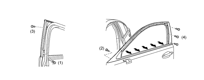
for Type A:
-
Install the front door belt moulding sub-assembly LH with the 6 screws.
Tech Tips
Install the screws in the order shown in the illustration.
-
Tighten the 5 belt line screws indicated by the arrows in the illustration.
-
-
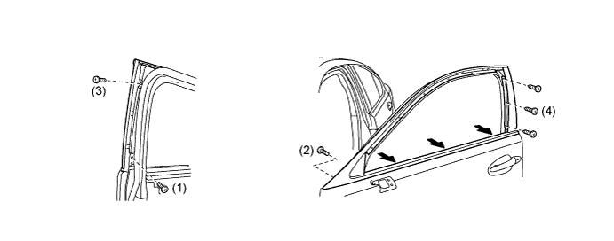
for Type B:
-
Install the front door belt moulding sub-assembly LH with the 6 screws.
Tech Tips
Install the screws in the order shown in the illustration.
-
Tighten the 3 belt line screws indicated by the arrows in the illustration.
-
-
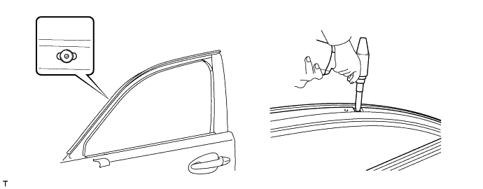
Install a nose piece to an air riveter or hand riveter. Then insert the mandrel part of a new 4 mm waterproof rivet into the nose piece.
-
Using the air riveter or hand riveter, install the rivet shown in the illustration.
Tech Tips
-
The rivet is for fixing the front door belt moulding in place.
-
If the rivet cannot be cut, pull it once and cut it.
Note
-
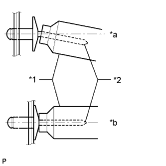
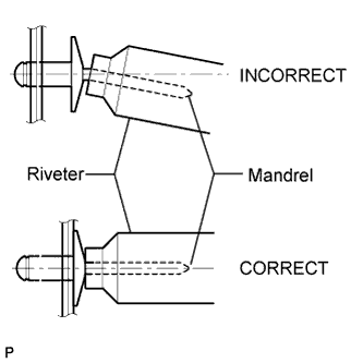
Do not pry the rivet with the riveter as this will cause damage to the riveter and mandrel.
Text in Illustration *1 Riveter *2 Mandrel *a INCORRECT *b CORRECT -
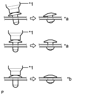
Confirm that the rivets are seated properly against the front door outside moulding.
-
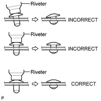
Do not tilt the riveter when installing the rivet to the front door outside moulding.
-
Do not leave any space between the rivet head and front door outside moulding.
Text in Illustration *1 Riveter *a INCORRECT *b CORRECT -
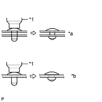
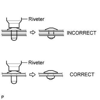
Do not leave any space between the front door outside moulding and front door panel. Firmly hold together the 2 items while installing the rivet.
Text in Illustration *1 Riveter *a INCORRECT *b CORRECT
-
-
-
INSTALL FRONT DOOR FRONT LOWER FRAME UPPER COVER LH
-
Attach the 2 clips to install the front door front lower frame upper cover LH.
-
-
INSTALL FRONT DOOR GLASS RUN LH
-
Install the front door glass run LH.
-
-
INSTALL FRONT DOOR GLASS SUB-ASSEMBLY LH
-
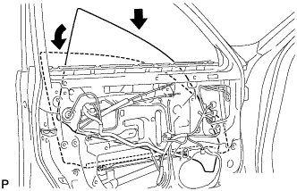
Insert the front door glass sub-assembly LH into the door panel along the glass run as indicated by the arrows in the illustration.
Note
Be careful not to damage the glass.
-
Install the front door glass sub-assembly LH to the front door window regulator sub-assembly LH with the 2 bolts.
- Torque:
- 5.5 N*m { 56 kgf*cm, 49 in.*lbf }
-
Install the hole plug.
-
-
INSTALL FRONT DOOR SERVICE HOLE COVER LH
-
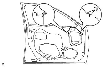
Apply new butyl tape to the door.
-
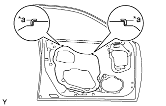
Text in Illustration *a Reference Point Install a new front door service hole cover LH using the reference points on the front door panel.
Tech Tips
-
When installing the service hole cover, pull the links and connectors through the service hole cover.
-
There should be no wrinkles or folds after attaching the service hole cover.
-
After attaching the service hole cover, check the sealing quality.
-
-
-
INSTALL FRONT DOOR WINDOW FRONT FRAME MOULDING LH
-
Attach the clip to install the window frame moulding.
-
Install a nose piece to an air riveter or hand riveter. Then insert the mandrel part of a new φ4 mm waterproof rivet into the nose piece.
-
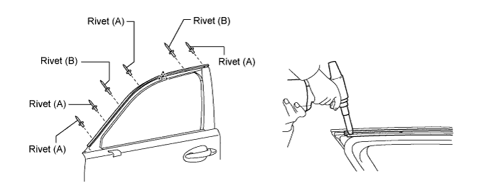
Using the air riveter or hand riveter, install the 6 rivets shown in the illustration.
Tech Tips
-
Using the air riveter or hand riveter, install the 6 rivets shown in the illustration.
Rivet Rivet Type (A) Short Type or Long Type (B) Long Type -
If the rivet cannot be cut, pull it once and cut it.
Note
-
Do not pry the rivet with the riveter, as this will cause damage to the riveter and mandrel.
-
Confirm that the rivets are seated properly against the moulding.
-
Do not tilt the riveter when installing the rivet to the moulding.
-
Do not leave any space between the rivet head and moulding.
-
Do not leave any space between the moulding and door frame. Firmly hold together the 2 items while installing the rivet.
-
-
-
INSTALL FRONT DOOR WEATHERSTRIP LH
-
Clean the front door surface.
-
Remove the double-sided tape from the front door.
-
Wipe off any tape adhesive residue with cleaner.
-
-
Install a new front door weatherstrip.
-
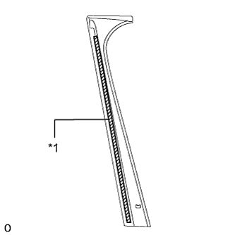
Remove the peeling paper from the face of the front door weatherstrip.
Tech Tips
After removing the peeling paper, keep the exposed adhesive free from foreign matter.
-
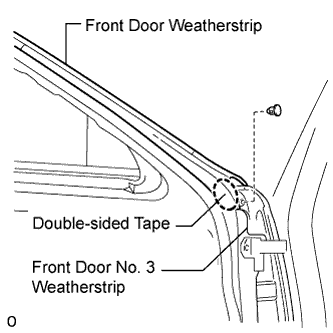
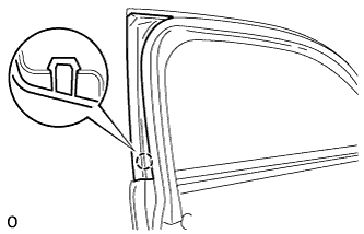
Install the front door weatherstrip with the clip.
Tech Tips
Lift up the front door No. 3 weather strip to install the front door weatherstrip, as the front door weatherstrip affixes to the inner side of the front door No. 3 weatherstrip.
-
-
-
INSTALL FRONT DOOR BELT MOULDING REAR END COVER LH
-
Text in Illustration *1 Double-sided Tape Place double-sided tape on the front door belt moulding end cover rear LH as shown in the illustration.
-
Attach the claw to install the front door belt moulding end cover rear LH.
-
-
INSTALL DOOR FRAME GARNISH LH
-
Install the door frame garnish LH with the 2 clips.
-
-
INSTALL FRONT DOOR TRIM COVER LH
-
Attach the 5 clips to install the front door trim cover LH.
-
Install the cushion.
-
-
INSTALL FRONT DOOR GLASS INNER WEATHERSTRIP LH
-
Install the front door glass inner weatherstrip LH.
-
-
INSTALL OUTER REAR VIEW MIRROR ASSEMBLY LH
-
INSTALL FRONT DOOR NO. 2 SERVICE HOLE COVER LH
-
Apply new butyl tape to the door.
-
Text in Illustration *a Reference Point Install a new front door No. 2 service hole cover LH using the reference points on the front door panel.
Tech Tips
-
When installing the service hole cover, pull the links and connectors through the service hole cover.
-
There should be no wrinkles or folds after attaching the service hole cover.
-
After attaching the service hole cover, check the sealing quality.
-
-
-
INSTALL FRONT MULTIPLEX NETWORK DOOR ECU LH
-
Install the front multiplex network door ECU LH to the door panel with the 2 screws.
-
Connect the 3 connectors.
-
-
INSTALL FRONT DOOR TRIM BOARD SUB-ASSEMBLY LH
-
Connect the connector.
-
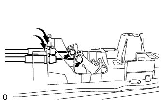
Connect the 2 cables to the inside handle.
-
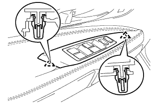
Attach the 13 clips to install the front door trim board sub-assembly LH.
-
Install the 3 screws.
-
-
INSTALL POWER WINDOW REGULATOR MASTER SWITCH ASSEMBLY WITH FRONT DOOR ARMREST BASE PANEL
-
Connect the connector.
-
Attach the 2 claws to install the power window regulator master switch assembly with front door armrest base panel.
-
-
INSTALL FRONT DOOR INSIDE HANDLE BEZEL PLUG LH
-
Attach the 3 claws to install the front door inside handle bezel plug LH.
-
-
CONNECT CABLE TO NEGATIVE BATTERY TERMINAL
Note
When disconnecting the cable, some systems need to be initialized after the cable is reconnected Click here.
-
INSTALL COWL TOP VENTILATOR LOUVER RH
-

Install the 6 clips and cowl top ventilator louver RH.
Note
Be sure to install the cowl top ventilator louver RH properly. If it is not installed properly, water may enter the engine room and cause malfunctions.
-