DOOR CLOSER SYSTEM TERMINALS OF ECU

-
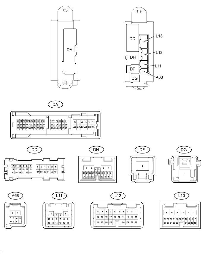
CHECK MAIN BODY ECU (DRIVER SIDE JUNCTION BLOCK)
-
DiscFnnect the DA, DD, L11, L12 and L13 ECU connectors.
-
Measure the resistance and voltage according to the value(s) in the table below.
Terminal No. (Symbols) Wiring Color Terminal Description Condition Specified Condition DA-40 (GND1) - Body ground W-B - Body ground Ground Always Below 1 Ω DA-40 (GND2) - Body ground W-B - Body ground Ground Always Below 1 Ω L11-1 (GND3) - DA-41 (GND1) W-B - Body ground Ground Always Below 1 Ω L13-24 (DCTY) - Body ground W - Body ground Driver side door courtesy light switch signal Driver side door open Below 1 Ω L13-24 (DCTY) - Body ground W - Body ground Driver side door courtesy light switch signal Driver side door closed 10 kΩ or higher L12-21 (PCTY) - Body ground L - Body ground Front passenger side door courtesy light switch signal Front passenger side door courtesy light switch open Below 1 Ω L12-21 (PCTY) - Body ground L - Body ground Front passenger side door courtesy light switch signal Front passenger side door courtesy light switch closed 10 kΩ or higher DD-12 (LCTY) - Body ground L - Body ground Rear door LH side door courtesy light switch signal Rear door LH side door courtesy light switch open Below 1 Ω DD-12 (LCTY) - Body ground L - Body ground Rear door LH side door courtesy light switch signal Rear door LH side door courtesy light switch closed 10 kΩ or higher L12-7 (RCTY) - Body ground R - Body ground Rear door RH side door courtesy light switch signal Rear door RH side door courtesy light switch open Below 1 Ω L12-7 (RCTY) - Body ground R - Body ground Rear door RH side door courtesy light switch signal Rear door RH side door courtesy light switch closed 10 kΩ or higher L12-1 (AM2) - Body ground W - Body ground Power supply Always 11 to 14 V L13-6 (AM1) - Body ground W - Body ground Power supply Always 11 to 14 V
-
If the result is not as specified, there may be a malfunction on the wire harness side.
-
-
-
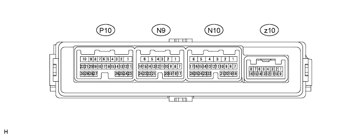
CHECK FRONT DOOR ECU LH
-
Disconnect the N10 ECU connector.
-
Measure the resistance and voltage according to the value(s) in the table below.
Terminal No. (Symbols) Wiring Color Terminal Description Condition Specified Condition N10-1 (GND1) - Body ground W-B - Body ground Ground Always Below 1 Ω N10-6 (BDR) - Body ground BE - Body ground Power supply circuit Always 11 to 14 V N10-11 (CPUB) - Body ground B - Body ground*1
R - Body ground*2
Power supply circuit Always 11 to 14 V Tech Tips
*1: for LHD
*2: for RHD
-
If the result is not as specified, there may be a malfunction on the wire harness side.
-
-
Reconnect the N10 ECU connector.
-
Measure the voltage according to the value(s) in the table below.
Terminal No. (Symbols) Wiring Color Terminal Description Condition Specified Condition N9-5 (A2+) - N9-6 (A2-) L - G Front door closer motor circuit Driver side door open → Fully closed (Closer operation) Below 1 V →
11 to 14 V →
Below 1 V
N9-7 (POLE) - N9-15 (CPSE) V - P Pawl switch signal input Driver side door open → Fully closed (Closer operation) 11 to 14 V →
Below 1 V →
11 to 14 V →
Below 1 V →
11 to 14 V
N9-8 (HALF) - N9-15 (CPSE) BE - P Half latch switch signal input Driver side door open → Fully closed (Closer operation) Below 1 V →
11 to 14 V
N9-9 (FULL) - N9-15 (CPSE) Y - P Full latch switch signal input Driver side door open → Fully closed (Closer operation) Below 1 V →
11 to 14 V
N9-18 (INIT) - N9-15 (CPSE) L - P Initial position switch signal input Driver side door open → Fully closed (Closer operation) 11 to 14 V →
Below 1 V →
11 to 14 V
N9-19 (HNDL) - N9-15 (CPSE) G - P Handle switch signal input Driver side door outside or inside handle not pulled 11 to 14 V Driver side door outside or inside handle pulled Below 1 V
-
If the result is not as specified, the ECU may have a malfunction.
-
-
-
CHECK FRONT DOOR ECU RH

-
Disconnect the N1 ECU connector.
-
Measure the resistance and voltage according to the value(s) in the table below.
Terminal No. (Symbols) Wiring Color Terminal Description Condition Specified Condition N1-1 (GND1) - Body ground W-B - Body ground Ground Always Below 1 Ω N1-6 (BDR) - Body ground BE - Body ground Power supply circuit Always 11 to 14 V N1-11 (CPUB) - Body ground R - Body ground*1
B - Body ground*2
Power supply circuit Always 11 to 14 V Tech Tips
*1: for LHD
*2: for RHD
-
If the result is not as specified, there may be a malfunction on the wire harness side.
-
-
Reconnect the N1 ECU connector.
-
Measure the voltage according to the value(s) in the table below.
Terminal No. (Symbols) Wiring Color Terminal Description Condition Specified Condition N2-5 (A2+) - N2-6 (A2-) L - G Front door closer motor circuit Front passenger side door open → Fully closed (Closer operation) Below 1 V →
11 to 14 V →
Below 1 V
N2-7 (POLE) - N2-15 (CPSE) V - P Pawl switch signal input Front passenger side door open → Fully closed (Closer operation) 11 to 14 V →
Below 1 V →
11 to 14 V →
Below 1 V →
11 to 14 V
N2-8 (HALF) - N2-15 (CPSE) BE - P Half-latch switch signal input Front passenger side door open → Fully closed (Closer operation) Below 1 V →
11 to 14 V
N2-9 (FULL) - N2-15 (CPSE) Y - P Full-latch switch signal input Front passenger side door open → Fully closed (Closer operation) Below 1 V →
11 to 14 V
N2-18 (INIT) - N2-15 (CPSE) L - P Initial position switch signal input Front passenger side door open → Fully closed (Closer operation) 11 to 14 V →
Below 1 V →
11 to 14 V
N2-19 (HNDL) - N2-15 (CPSE) G - P Handle switch signal input Front passenger side door outside or inside handle not pulled 11 to 14 V Front passenger side door outside or inside handle pulled Below 1 V
-
If the result is not as specified, the ECU may be malfunctioning.
-
-
-
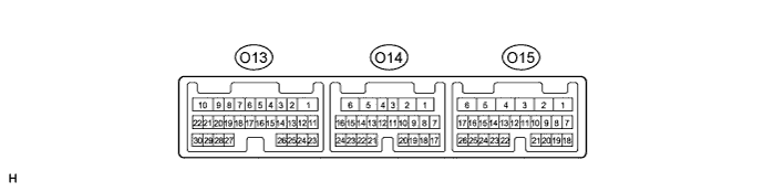
CHECK REAR DOOR ECU LH
-
Disconnect the O14 ECU connector.
-
Measure the resistance and voltage according to the value(s) in the table below.
Terminal No. (Symbols) Wiring Color Terminal Description Condition Specified Condition O14-1 (GND1) - Body ground W-B - Body ground Ground Always Below 1 Ω O14-6 (BDR) - Body ground L - Body ground Power supply circuit Always 11 to 14 V O14-11 (CPUB) - Body ground R - Body ground Power supply circuit Always 11 to 14 V
-
If the result is not as specified, there may be a malfunction on the wire harness side.
-
-
Reconnect the O14 ECU connector.
-
Measure the voltage according to the value(s) in the table below.
Terminal No. (Symbols) Wiring Color Terminal Description Condition Specified Condition O13-3 (A2+) - O13-4 (A2-) L - G Front door closer motor circuit Rear door LH side open → Fully closed (Closer operation) Below 1 V →
11 to 14 V →
Below 1 V
O13-7 (POLE) - O13-15 (CPSE) V - P Pawl switch signal input Rear door LH side open → Fully closed (Closer operation) 11 to 14 V →
Below 1 V →
11 to 14 V →
Below 1 V →
11 to 14 V
O13-8 (HALF) - O13-15 (CPSE) BE - P Half latch switch signal input Rear door LH side open → Fully closed (Closer operation) Below 1 V →
11 to 14 V
O13-9 (FULL) - O13-15 (CPSE) Y - P Full latch switch signal input Rear door LH side open → Fully closed (Closer operation) Below 1 V →
11 to 14 V
O13-16 (INIT) - O13-15 (CPSE) L - P Initial position switch signal input Rear door LH side open → Fully closed (Closer operation) 11 to 14 V →
Below 1 V →
11 to 14 V
O13-24 (HNDL) - O13-15 (CPSE) G - P Handle switch signal input Rear door LH side outside or inside handle not pulled 11 to 14 V Rear door LH side outside or inside handle pulled Below 1 V
-
If the result is not as specified, the ECU may have a malfunction.
-
-
-
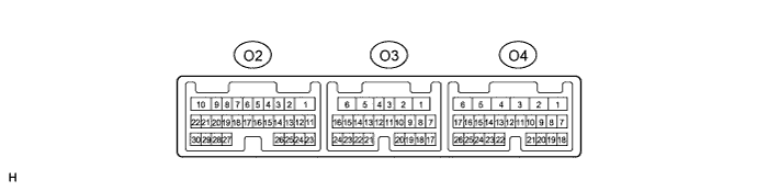
CHECK REAR DOOR ECU RH
-
Disconnect the O3 ECU connector.
-
Measure the resistance and voltage according to the value(s) in the table below.
Terminal No. (Symbols) Wiring Color Terminal Description Condition Specified Condition O3-1 (GND1) - Body ground W-B - Body ground Ground Always Below 1 Ω O3-6 (BOR) - Body ground L - Body ground Power supply circuit Always 11 to 14 V O3-11 (CPUB) - Body ground R - Body ground Power supply circuit Always 11 to 14 V
-
If the result is not as specified, there may be a malfunction on the wire harness side.
-
-
Reconnect the O3 ECU connector.
-
Measure the voltage according to the value(s) in the table below.
Terminal No. (Symbols) Wiring Color Terminal Description Condition Specified Condition O4-3 (A2+) - O4-4 (A2-) L - G Front door closer motor circuit Rear door RH side open → Fully closed (Closer operation) Below 1 V →
11 to 14 V →
Below 1 V
O4-7 (POLE) - O4-15 (CPSE) V - P Pawl switch signal input Rear door RH side open → Fully closed (Closer operation) 11 to 14 V →
Below 1 V →
11 to 14 V →
Below 1 V →
11 to 14 V
O4-8 (HALF) - O4-15 (CPSE) BE - P Half latch switch signal input Rear door RH side open → Fully closed (Closer operation) Below 1 V →
11 to 14 V
O4-9 (FULL) - O4-15 (CPSE) Y - P Full latch switch signal input Rear door RH side open → Fully closed (Closer operation) Below 1 V →
11 to 14 V
O4-16 (INIT) - O4-15 (CPSE) L - P Initial position switch signal input Rear door RH side open → Fully closed (Closer operation) 11 to 14 V →
Below 1 V →
11 to 14 V
O4-24 (HNDL) - O4-15 (CPSE) G - P Handle switch signal input Rear door RH side outside or inside handle not pulled 11 to 14 V Rear door RH side outside or inside handle pulled Below 1 V
-
If the result is not as specified, the ECU may have a malfunction.
-
-