SEAT VIBRATION SYSTEM Seatback Mat does not Operate
DESCRIPTION
The seat vibration module receives power from the battery, and operates the rear seatback mat. Also, the seat vibration module and seat vibrator switch are controlled through LIN communication signals. If an error is detected, all system operations stop and only SW1 can be operated (all other switches cannot be operated). After the error is corrected, the system enters stop mode.
| Blinking Area | Detection Condition / Cause | Display |
|---|---|---|
| LED6 blinks (Intensity - High) |
|
|
| LED7 blinks (Intensity - Normal) |
|
|
| LED8 blinks (Intensity - Low) |
|
|
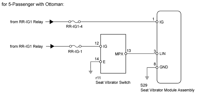
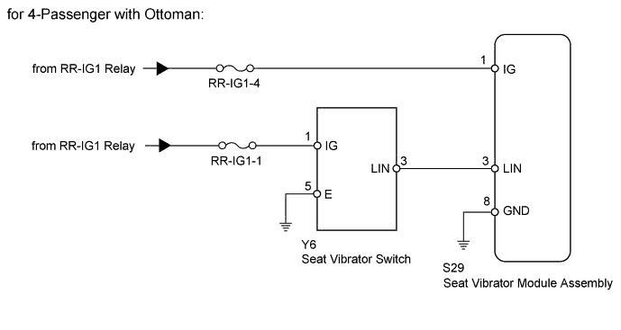
WIRING DIAGRAM
INSPECTION PROCEDURE
Tech Tips
Refer to system description Click here.
PROCEDURE
-
CHECK BLINKING CONDITION OF LED7
-
5 seconds after the seat vibrator switch SW1 is pressed, check if LED7 blinks.
Result Result Proceed to Blinks A Does not blink B
B 
CHECK BLINKING CONDITION OF LED6 Click here
A 
-
-
CHECK HARNESS AND CONNECTOR (SEAT VIBRATOR MODULE - BATTERY AND BODY GROUND)
-
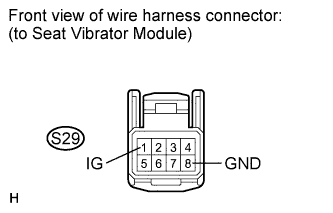
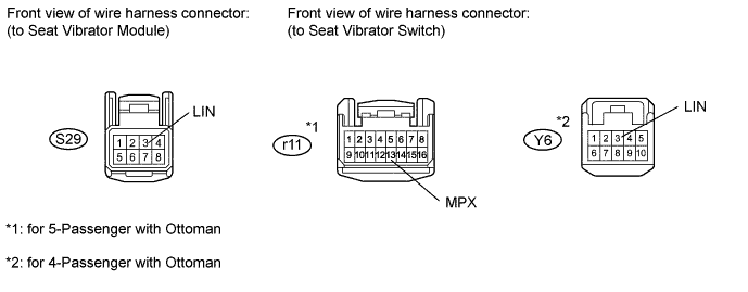
Disconnect the S29 seat vibrator module connector.
-
Measure the voltage and resistance according to the values in the table below.
Standard voltage Tester Connection Switch Condition Specified Condition S29-1 (IG) - Body ground Engine switch on (IG) 11 to 14 V Standard resistance Tester Connection Condition Specified Condition S29-8 (GND) - Body ground Always Below 1 Ω
NG 
REPAIR OR REPLACE HARNESS OR CONNECTOR
OK 
REPLACE SEAT VIBRATOR MODULE ASSEMBLY Click here
-
-
CHECK BLINKING CONDITION OF LED6
-
5 seconds after the seat vibrator switch SW1 is pressed, check if LED6 blinks.
Result Result Proceed to Blinks A Does not blink B
B
CHECK SEAT VIBRATOR SWITCH Click here
A
-
-
CHECK HARNESS AND CONNECTOR (SEAT VIBRATOR SWITCH - BATTERY AND BODY GROUND)
-
for 5-Passenger with Ottoman:
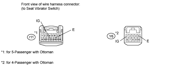
Disconnect the r11 switch connector.
-
for 4-Passenger with Ottoman:
Disconnect the Y6 switch connector.
-
Measure the voltage and resistance according to the values in the table below.
Standard voltage for 5-Passenger with Ottoman Tester Connection Switch Condition Specified Condition r11-12 (IG) - Body ground Engine switch on (IG) 11 to 14 V for 4-Passenger with Ottoman Tester Connection Switch Condition Specified Condition Y6-1 (IG) - Body ground Engine switch on (IG) 11 to 14 V Standard resistance for 5-Passenger with Ottoman Tester Connection Condition Specified Condition r11-14 (E) - Body ground Always Below 1 Ω for 4-Passenger with Ottoman Tester Connection Condition Specified Condition Y6-5 (E) - Body ground Always Below 1 Ω
NG
REPAIR OR REPLACE HARNESS OR CONNECTOR
OK
-
-
CHECK HARNESS AND CONNECTOR (SEAT VIBRATOR SWITCH - SEAT VIBRATOR MODULE)
-
Disconnect the S29 seat vibrator module connector.
-
for 5-Passenger with Ottoman:
Disconnect the r11 switch connector.
-
for 4-Passenger with Ottoman:
Disconnect the Y6 switch connector.
-
Measure the resistance according to the values in the table below.
Standard resistance for 5-Passenger with Ottoman Tester Connection Condition Specified Condition r11-13 (MPX) - S29-3 (LIN) Always Below 1 Ω for 4-Passenger with Ottoman Tester Connection Condition Specified Condition Y6-3 (LIN) - S29-3 (LIN) Always Below 1 Ω
NG
REPAIR OR REPLACE HARNESS OR CONNECTOR
OK
-
-
CHECK SEAT VIBRATOR SWITCH (OPERATION)
-
Replace the seat vibrator switch with a new or normally operating one. Perform an operation inspection.
OK Seatback mat operates normally.
NG
REPLACE SEAT VIBRATOR MODULE ASSEMBLY Click here
OK
END (SEAT VIBRATOR SWITCH IS DEFECTIVE)
-
-
CHECK SEAT VIBRATOR SWITCH
-
When the seat vibrator switch's air operation is selected, check that the respective seat vibrator switch LEDs illuminate.
Result Result Proceed to Illuminate A Do not illuminate B
B
CHECK BLINKING CONDITION OF LED8 Click here
A
-
-
CHECK SEAT VIBRATOR MODULE ASSEMBLY (OPERATION)
-
Replace the seat vibrator module with a new or normally operating one. Perform an operation inspection.
OK Seatback mat operates normally.
NG
CHECK AIR HOSE Click here
OK
END (SEAT VIBRATION MODULE ASSEMBLY IS DEFECTIVE)
-
-
CHECK AIR HOSE
-
Replace the air hose with a new or normally operating one. Perform an operation inspection.
OK Seatback mat operates normally.
NG
REPLACE SUB SEATBACK PLATE SUB-ASSEMBLY Click here
OK
END (AIR HOSE IS DEFECTIVE)
-
-
CHECK BLINKING CONDITION OF LED8
-
5 seconds after the seat vibrator switch SW1 is pressed, check if LED8 blinks.
Result Result Proceed to Blinks A Does not blink B
B
CHECK SEAT VIBRATOR SWITCH (OPERATION) Click here
A
REPLACE SEAT VIBRATOR MODULE ASSEMBLY Click here
-
-
CHECK SEAT VIBRATOR SWITCH (OPERATION)
-
Replace the seat vibrator switch with a new or normally operating one. Perform an operation inspection.
OK All switches on seat vibrator switch operate normally.
NG
REPLACE SEAT VIBRATOR MODULE ASSEMBLY Click here
OK
END (SEAT VIBRATOR SWITCH IS DEFECTIVE)
-