REAR POWER SEAT CONTROL SYSTEM Door Open Linked Operation cannot be Canceled
DESCRIPTION
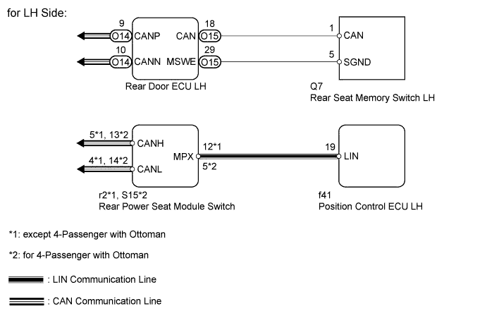
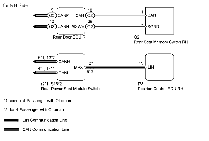
When the rear seat memory switch's C switch is pressed, a C switch signal is sent from the rear door ECU to the rear power seat switch through CAN communication. Then the rear power seat switch sends the C switch signal to the position control ECU through the LIN line. When the position control ECU receives the C switch signal, the door open linked return operation is stopped.
WIRING DIAGRAM
INSPECTION PROCEDURE
PROCEDURE
-
READ VALUE USING INTELLIGENT TESTER (REAR SEAT INITIALIZE)
-
Check the Data List for proper functioning of the seat memory switch.
Rear Left Seat Tester Display Measurement Item/Range Normal Condition Diagnostic Note Rear Seat Initialize Rear seat initialization information / Init or No Init Init: Initialization completed No Init: Initialization not yet performed - Rear Right Seat Tester Display Measurement Item/Range Normal Condition Diagnostic Note Rear Seat Initialize Rear seat initialization information / Init or No Init Init: Initialization completed No Init: Initialization not yet performed - OK On tester screen, each item changes between ON and OFF according to above chart. Result Result Proceed to OK (for LH Side) A OK (for RH Side) B NG (for LH Side) C NG (for RH Side) D Tech Tips
-
for LH Side (w/o Ottoman):
If it is necessary to refer to the rear seat assembly, refer to the following procedures Click here.
-
for LH Side (w/ Ottoman):
If it is necessary to refer to the rear seat assembly, refer to the following procedures Click here.
-
for RH Side (w/o Ottoman):
If it is necessary to refer to the rear seat assembly, refer to the following procedures Click here.
-
for RH Side (w/ Ottoman):
If it is necessary to refer to the rear seat assembly, refer to the following procedures Click here.
-
B 
REPLACE POSITION CONTROL ECU RH
C 
INSPECT REAR SEAT MEMORY SWITCH LH Click here
D
INSPECT REAR SEAT MEMORY SWITCH RH Click here
A 
REPLACE POSITION CONTROL ECU LH
-
-
INSPECT REAR SEAT MEMORY SWITCH LH
-
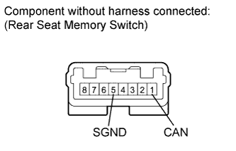
Remove the memory switch.
-
Measure the resistance according to the values in the table below.
Standard resistance Tester Connection Switch Condition Specified Condition 1 (CAN) - 5 (SGND) C switch pressed Below 1 Ω
NG
REPLACE REAR SEAT MEMORY SWITCH LH Click here
OK 
-
-
CHECK HARNESS AND CONNECTOR (REAR DOOR ECU LH - REAR SEAT MEMORY SWITCH AND BODY GROUND)
-
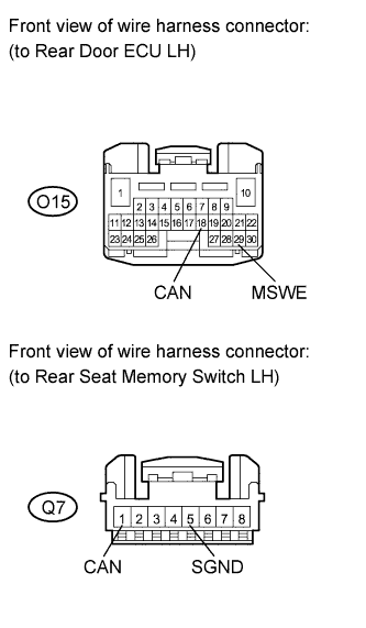
Disconnect the O15 ECU connector.
-
Disconnect the Q7 switch connector.
-
Measure the resistance according to the values in the table below.
Standard resistance Tester Connection Condition Specified Condition O15-18 (CAN) - Q7-1 (CAN) Always Below 1 Ω O15-29 (MSWE) - Q7-5 (SGND) Always Below 1 Ω O15-18 (CAN) - Body ground Always 10 kΩ or higher O15-29 (MSWE) - Body ground Always 10 kΩ or higher
NG
REPAIR OR REPLACE HARNESS OR CONNECTOR
OK
REPLACE REAR DOOR ECU LH Click here
-
-
INSPECT REAR SEAT MEMORY SWITCH RH
-
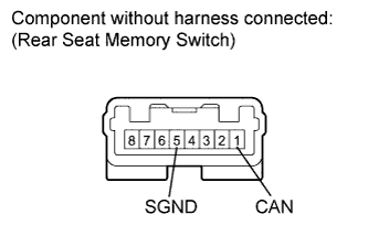
Remove the memory switch.
-
Measure the resistance according to the values in the table below.
Standard resistance Tester Connection Switch Condition Specified Condition 1 (CAN) - 5 (SGND) C switch pressed Below 1 Ω
NG
REPLACE REAR SEAT MEMORY SWITCH RH Click here
OK
-
-
CHECK HARNESS AND CONNECTOR (REAR DOOR ECU RH - REAR SEAT MEMORY SWITCH AND BODY GROUND)
-
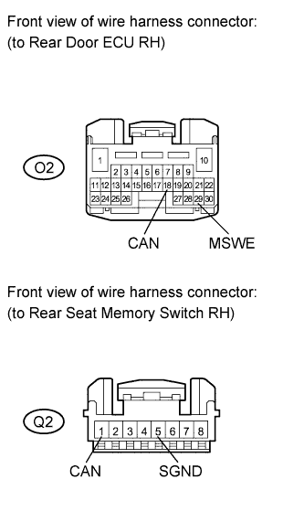
Disconnect the O2 ECU connector.
-
Disconnect the Q2 switch connector.
-
Measure the resistance according to the values in the table below.
Standard resistance Tester Connection Condition Specified Condition O2-18 (CAN) - Q2-1 (CAN) Always Below 1 Ω O2-29 (MSWE) - Q2-5 (SGND) Always Below 1 Ω O2-18 (CAN) - Body ground Always 10 kΩ or higher O2-29 (MSWE) - Body ground Always 10 kΩ or higher
NG
REPAIR OR REPLACE HARNESS OR CONNECTOR
OK
REPLACE REAR DOOR ECU RH Click here
-