REAR POWER SEAT CONTROL SYSTEM Power Seat Position is not Memorized
DESCRIPTION
When the rear seat memory switch's SET is pressed, each position sensor's value is recorded into the position control ECU.
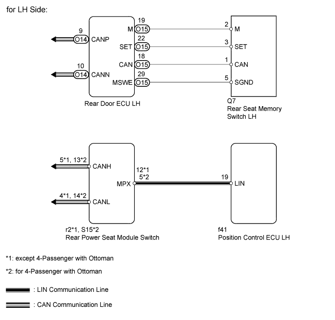
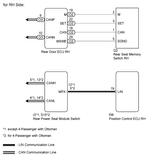
WIRING DIAGRAM
INSPECTION PROCEDURE
PROCEDURE
-
CHECK REAR POWER SEAT CONTROL FUNCTION
-
Operate the rear power seat switch and check that each power seat function operates normally.
OK Each function operates normally.
NG 
GO TO PROBLEM SYMPTOMS TABLE Click here
OK 
-
-
CHECK REAR SEAT RETURN FUNCTION
-
When the rear door is opened, check that the door open linked return operation operates.
OK Door open linked return operation operates normally.
NG
GO TO PROBLEM SYMPTOMS TABLE Click here
OK
-
-
CHECK REAR SEAT MEMORY FUNCTION
-
Perform a memory operation correctly. Check that the buzzer sounds to indicate the completion of the memory operation.
OK Seat position is memorized normally.
OK
SYSTEM IS OK
NG
-
-
READ VALUE USING INTELLIGENT TESTER (SEAT MEMORY SWITCH)
-
Check the Data List for proper functioning of the seat memory switch.
Rear Left Seat Tester Display Measurement Item/Range Normal Condition Diagnostic Note SET Switch Seat memory SET switch signal / ON or OFF ON: Memory SET switch is ON
OFF: Memory SET switch is OFF
- M1 Switch Seat memory switch M signal / ON or OFF ON: Seat memory switch M is ON
OFF: Seat memory switch M is OFF
- Rear Right Seat Tester Display Measurement Item/Range Normal Condition Diagnostic Note SET Switch Seat memory SET switch signal / ON or OFF ON: Memory SET switch is ON
OFF: Memory SET switch is OFF
- M1 Switch Seat memory switch M signal / ON or OFF ON: Seat memory switch M is ON
OFF: Seat memory switch M is OFF
- OK On tester screen, each item changes between ON and OFF according to above chart. Result Result Proceed to OK (for LH Side) A OK (for RH Side) B NG (for LH Side) C NG (for RH Side) D Tech Tips
-
for LH Side (w/o Ottoman):
If it is necessary to refer to the rear seat assembly, refer to the following procedures Click here.
-
for LH Side (w/ Ottoman):
If it is necessary to refer to the rear seat assembly, refer to the following procedures Click here.
-
for RH Side (w/o Ottoman):
If it is necessary to refer to the rear seat assembly, refer to the following procedures Click here.
-
for RH Side (w/ Ottoman):
If it is necessary to refer to the rear seat assembly, refer to the following procedures Click here.
-
B
REPLACE POSITION CONTROL ECU RH
C 
INSPECT REAR SEAT MEMORY SWITCH LH Click here
D
INSPECT REAR SEAT MEMORY SWITCH RH Click here
A 
REPLACE POSITION CONTROL ECU LH
-
-
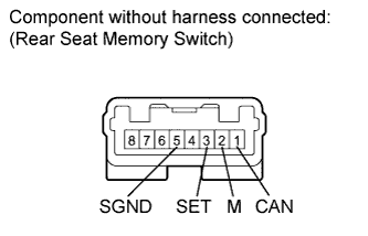
INSPECT REAR SEAT MEMORY SWITCH LH
-
Remove the memory switch Click here.
-
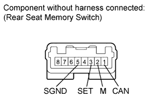
Measure the resistance according to the values in the table below.
Standard resistance Tester Connection Switch Condition Specified Condition 3 (SET) - 5 (SGND) SET switch pressed Below 1 Ω 2 (M) - 5 (SGND) M switch pressed Below 1 Ω 1 (CAN) - 5 (SGND) C switch pressed Below 1 Ω
NG
REPLACE REAR SEAT MEMORY SWITCH LH Click here
OK
-
-
CHECK HARNESS AND CONNECTOR (REAR DOOR ECU RH - REAR SEAT MEMORY SWITCH LH AND BODY GROUND)
-
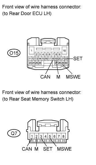
Disconnect the O15 ECU connector.
-
Disconnect the Q7 switch connector.
-
Measure the resistance according to the values in the table below.
Standard resistance Tester Connection Condition Specified Condition O15-22 (SET) - Q7-3 (SET) Always Below 1 Ω O15-19 (M) - Q7-2 (M) Always Below 1 Ω O15-18 (CAN) - Q7-1 (CAN) Always Below 1 Ω O15-29 (MSWE) - Q7-5 (MSWE) Always Below 1 Ω O15-22 (SET) - Body ground Always 10 kΩ or higher O15-19 (M) - Body ground Always 10 kΩ or higher O15-18 (CAN) - Body ground Always 10 kΩ or higher O15-29 (MSWE) - Body ground Always 10 kΩ or higher
NG
REPAIR OR REPLACE HARNESS OR CONNECTOR
OK
REPLACE REAR DOOR ECU LH Click here
-
-
INSPECT REAR SEAT MEMORY SWITCH RH
-
Remove the memory switch Click here.
-
Measure the resistance according to the values in the table below.
Standard resistance Tester Connection Switch Condition Specified Condition 3 (SET) - 5 (SGND) SET switch pressed Below 1 Ω 2 (M) - 5 (SGND) M switch pressed Below 1 Ω 1 (CAN) - 5 (SGND) C switch pressed Below 1 Ω
NG
REPLACE REAR SEAT MEMORY SWITCH RH Click here
OK
-
-
CHECK HARNESS AND CONNECTOR (REAR DOOR ECU RH - REAR SEAT MEMORY SWITCH RH AND BODY GROUND)
-

Disconnect the O2 ECU connector.
-
Disconnect the Q2 switch connector.
-
Measure the resistance according to the values in the table below.
Standard resistance Tester Connection Condition Specified Condition O2-22 (SET) - Q2-3 (SET) Always Below 1 Ω O2-19 (M) - Q2-2 (M) Always Below 1 Ω O2-18 (CAN) - Q2-1 (CAN) Always Below 1 Ω O2-29 (MSWE) - Q2-5 (MSWE) Always Below 1 Ω O2-22 (SET) - Body ground Always 10 kΩ or higher O2-19 (M) - Body ground Always 10 kΩ or higher O2-18 (CAN) - Body ground Always 10 kΩ or higher O2-29 (MSWE) - Body ground Always 10 kΩ or higher
NG
REPAIR OR REPLACE HARNESS OR CONNECTOR
OK
REPLACE REAR DOOR ECU RH Click here
-