FRONT POWER SEAT CONTROL SYSTEM Power Seat Position is not Memorized
DESCRIPTION
When the M1, M2 or M3 switch is pressed while the SET switch is pressed and held, or when the SET switch is pressed and then the M1, M2 or M3 switch is pressed within 3 seconds, the position value of each sensor is sent from the front door ECU to the front power seat switch (seat ECU) via CAN communication.
WIRING DIAGRAM
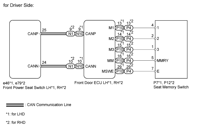
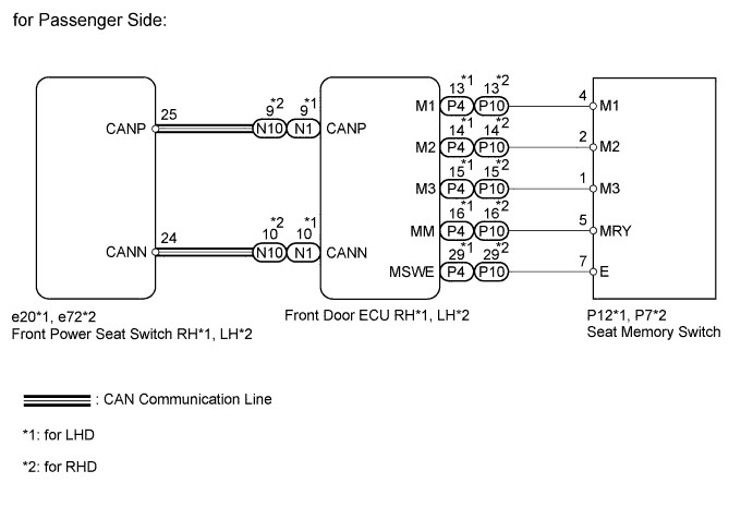
INSPECTION PROCEDURE
PROCEDURE
-
CHECK FRONT POWER SEAT CONTROL FUNCTION
-
Check that each function of the power seat operates normally by using the front power seat switches.
OK Each function of power seat operates normally by using seat switches.
NG 
GO TO PROBLEM SYMPTOMS TABLE Click here
OK 
-
-
CHECK SEAT MEMORY SWITCH FUNCTION
-
Perform a memory operation properly. Check that the buzzer sounds to indicate the completion of the memory operation.
Note
-
The seat position will not be recorded if the SET switch and 2 or more of the memory switches (for example, M1 and M2) are pressed simultaneously.
-
The seat position will not be recorded if a memory switch (M1, M2 or M3) is not pressed within 3 seconds of pressing the SET switch.
-
If a memorizing operation has failed, release all the switches. The seat memory function does not operate unless the switches are released.
OK Seat memory switch function operates normally. -
NG 
READ VALUE USING INTELLIGENT TESTER (SEAT MEMORY SWITCH) Click here
OK 
END
-
-
READ VALUE USING INTELLIGENT TESTER (SEAT MEMORY SWITCH)
-
Check the Data List for proper functioning of the seat memory switch.
Driver Door Tester Display Measurement Item/Range Normal Condition Diagnostic Note Seat Memory Set SW Seat memory set switch signal / ON or OFF ON: Memory set switch is ON
OFF: Memory set switch is OFF
- Seat Memory Switch1 Seat memory switch M1 signal / ON or OFF ON: Seat memory switch M1 is ON
OFF: Seat memory switch M1 is OFF
- Seat Memory Switch2 Seat memory switch M2 signal / ON or OFF ON: Seat memory switch M2 is ON
OFF: Seat memory switch M2 is OFF
- Seat Memory Switch3 Seat memory switch M3 signal / ON or OFF ON: Seat memory switch M3 is ON
OFF: Seat memory switch M3 is OFF
- Passenger Door Tester Display Measurement Item/Range Normal Condition Diagnostic Note Seat Memory Set SW Seat memory set switch signal / ON or OFF ON: Memory set switch is ON
OFF: Memory set switch is OFF
- Seat Memory Switch1 Seat memory switch M1 signal / ON or OFF ON: Seat memory switch M1 is ON
OFF: Seat memory switch M1 is OFF
- Seat Memory Switch2 Seat memory switch M2 signal / ON or OFF ON: Seat memory switch M2 is ON
OFF: Seat memory switch M2 is OFF
- Seat Memory Switch3 Seat memory switch M3 signal / ON or OFF ON: Seat memory switch M3 is ON
OFF: Seat memory switch M3 is OFF
- OK On tester screen, each item changes between ON and OFF according to above chart. Result Result Proceed to OK A NG (for Driver Side) B NG (for Passenger Side) C
B
INSPECT SEAT MEMORY SWITCH Click here
C
INSPECT SEAT MEMORY SWITCH Click here
A
-
-
READ VALUE USING INTELLIGENT TESTER (SEAT MEMORY SWITCH)
-
Check the Data List for proper functioning of the seat memory switch.
Driver Seat Tester Display Measurement Item/Range Normal Condition Diagnostic Note SET Switch Seat memory SET switch signal/ ON or OFF ON: Memory SET switch is ON
OFF: Memory SET switch is OFF
- M1 Switch Seat memory switch M1 signal/ ON or OFF ON: Seat memory switch M1 is ON
OFF: Seat memory switch M1 is OFF
- M2 Switch Seat memory switch M2 signal/ ON or OFF ON: Seat memory switch M2 is ON
OFF: Seat memory switch M2 is OFF
- M3 Switch Seat memory switch M3 signal/ ON or OFF ON: Seat memory switch M3 is ON
OFF: Seat memory switch M3 is OFF
- Passenger Seat Tester Display Measurement Item/Range Normal Condition Diagnostic Note SET Switch Seat memory SET switch signal/ ON or OFF ON: Memory SET switch is ON
OFF: Memory SET switch is OFF
- M1 Switch Seat memory switch M1 signal/ ON or OFF ON: Seat memory switch M1 is ON
OFF: Seat memory switch M1 is OFF
- M2 Switch Seat memory switch M2 signal/ ON or OFF ON: Seat memory switch M2 is ON
OFF: Seat memory switch M2 is OFF
- M3 Switch Seat memory switch M3 signal/ ON or OFF ON: Seat memory switch M3 is ON
OFF: Seat memory switch M3 is OFF
- OK On tester screen, each item changes between ON and OFF according to above chart. Result Result Proceed to OK (for Driver Side) A OK (for Passenger Side) B NG (for Driver Side) C NG (for Passenger Side) D
B
REPLACE FRONT POWER SEAT SWITCH (for Passenger Side) Click here
C
REPLACE FRONT DOOR ECU (for Driver Side) Click here
D
REPLACE FRONT DOOR ECU (for Passenger Side) Click here
A
REPLACE FRONT POWER SEAT SWITCH (for Driver Side) Click here
-
-
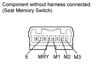
INSPECT SEAT MEMORY SWITCH
-
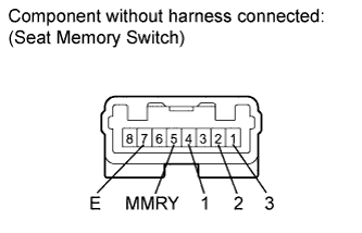
Remove the switch.
-
Measure the resistance according to the values in the table below.
Standard resistance for LHD Tester Connection Switch Condition Specified Condition 4 (1) - 7 (E) M1 switch pressed Below 1 Ω 2 (2) - 7 (E) M2 switch pressed Below 1 Ω 1 (3) - 7 (E) M3 switch pressed Below 1 Ω 5 (MMRY) - 7 (E) SET switch pressed Below 1 Ω for RHD Tester Connection Switch Condition Specified Condition 4 (1) - 7 (E) M1 switch pressed Below 1 Ω 2 (2) - 7 (E) M2 switch pressed Below 1 Ω 1 (3) - 7 (E) M3 switch pressed Below 1 Ω 5 (MMRY) - 7 (E) SET switch pressed Below 1 Ω
NG
REPLACE SEAT MEMORY SWITCH Click here
OK
-
-
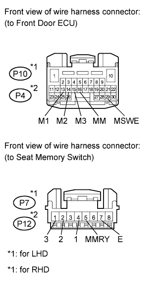
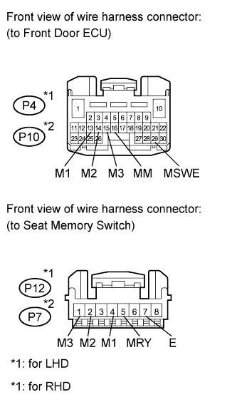
CHECK HARNESS AND CONNECTOR (FRONT DOOR ECU - SEAT MEMORY SWITCH)
-
for LHD:
-
Disconnect the P10 ECU connector.
-
Disconnect the P7 switch connector.
-
-
for RHD:
-
Disconnect the P4 ECU connector.
-
Disconnect the P12 switch connector.
-
-
Measure the resistance according to the values in the table below.
Standard resistance for LHD Tester Connection Condition Specified Condition P10-13 (M1) - P7-4 (1) Always Below 1 Ω P10-14 (M2) - P7-2 (2) Always Below 1 Ω P10-15 (M3) - P7-1 (3) Always Below 1 Ω P10-16 (MM) - P7-5 (MMRY) Always Below 1 Ω P10-29 (MSWE) - P7-7 (E) Always Below 1 Ω P10-13 (M1) - Body ground Always 10 kΩ or higher P10-14 (M2) - Body ground Always 10 kΩ or higher P10-15 (M3) - Body ground Always 10 kΩ or higher P10-16 (MM) - Body ground Always 10 kΩ or higher P10-29 (MSWE) - Body ground Always 10 kΩ or higher for RHD Tester Connection Condition Specified Condition P4-13 (M1) - P12-4 (1) Always Below 1 Ω P4-14 (M2) - P12-2 (2) Always Below 1 Ω P4-15 (M3) - P12-1 (3) Always Below 1 Ω P4-16 (MM) - P12-5 (MMRY) Always Below 1 Ω P4-29 (MSWE) - P12-7 (E) Always Below 1 Ω P4-13 (M1) - Body ground Always 10 kΩ or higher P4-14 (M2) - Body ground Always 10 kΩ or higher P4-15 (M3) - Body ground Always 10 kΩ or higher P4-16 (MM) - Body ground Always 10 kΩ or higher P4-29 (MSWE) - Body ground Always 10 kΩ or higher
NG
REPAIR OR REPLACE HARNESS OR CONNECTOR
OK
-
-
INSPECT SEAT MEMORY SWITCH
-
Remove the switch.
-
Measure the resistance according to the values in the table below.
Standard resistance for RHD Tester Connection Switch Condition Specified Condition 4 (M1) - 7 (E) M1 switch pressed Below 1 Ω 2 (M2) - 7 (E) M2 switch pressed Below 1 Ω 1 (M3) - 7 (E) M3 switch pressed Below 1 Ω 5 (MRY) - 7 (E) SET switch pressed Below 1 Ω for LHD Tester Connection Switch Condition Specified Condition 4 (M1) - 7 (E) M1 switch pressed Below 1 Ω 2 (M2) - 7 (E) M2 switch pressed Below 1 Ω 1 (M3) - 7 (E) M3 switch pressed Below 1 Ω 5 (MRY) - 7 (E) SET switch pressed Below 1 Ω
NG
REPLACE SEAT MEMORY SWITCH Click here
OK
-
-
CHECK HARNESS AND CONNECTOR (FRONT DOOR ECU - SEAT MEMORY SWITCH)
-
for LHD:
-
Disconnect the P4 ECU connector.
-
Disconnect the P12 switch connector.
-
-
for RHD:
-
Disconnect the P10 ECU connector.
-
Disconnect the P7 switch connector.
-
-
Measure the resistance according to the values in the table below.
Standard resistance for LHD Tester Connection Condition Specified Condition P4-13 (M1) - P12-4 (M1) Always Below 1 Ω P4-14 (M2) - P12-2 (M2) Always Below 1 Ω P4-15 (M3) - P12-1 (M3) Always Below 1 Ω P4-16 (MM) - P12-5 (MRY) Always Below 1 Ω P4-29 (MSWE) - P12-7 (E) Always Below 1 Ω P4-13 (M1) - Body ground Always 10 kΩ or higher P4-14 (M2) - Body ground Always 10 kΩ or higher P4-15 (M3) - Body ground Always 10 kΩ or higher P4-16 (MM) - Body ground Always 10 kΩ or higher P4-29 (MSWE) - Body ground Always 10 kΩ or higher for RHD Tester Connection Condition Specified Condition P10-13 (M1) - P7-4 (M1) Always Below 1 Ω P10-14 (M2) - P7-2 (M2) Always Below 1 Ω P10-15 (M3) - P7-1 (M3) Always Below 1 Ω P10-16 (MM) - P7-5 (MRY) Always Below 1 Ω P10-29 (MSWE) - P7-7 (E) Always Below 1 Ω P10-13 (M1) - Body ground Always 10 kΩ or higher P10-14 (M2) - Body ground Always 10 kΩ or higher P10-15 (M3) - Body ground Always 10 kΩ or higher P10-16 (MM) - Body ground Always 10 kΩ or higher P10-29 (MSWE) - Body ground Always 10 kΩ or higher
NG
REPAIR OR REPLACE HARNESS OR CONNECTOR
OK
REPLACE FRONT POWER SEAT SWITCH (for Passenger Side) Click here
-