FRONT POWER SEAT CONTROL SYSTEM Front Power Seat does not Operate with Front Power Seat Switch
DESCRIPTION
When a signal is input into the front power seat switch (seat ECU), the ECU manages the signals received from the front power seat switch LH and RH, and operates each motor. When 2 or more signals are input, the motors only operate when the signals are from the slide switch and reclining switch.
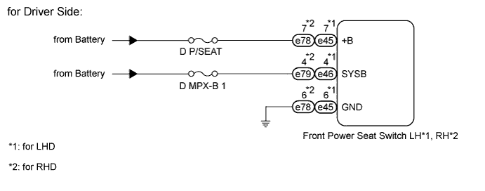
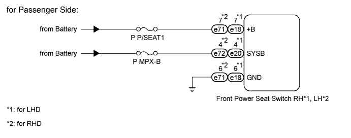
WIRING DIAGRAM
INSPECTION PROCEDURE
PROCEDURE
-
INSPECT FUSE
-
Remove the D P/SEAT and D MPX-B 1 fuses from the main body ECU.
-
Remove the P P/SEAT 1 and P MPX-B fuses from the passenger side junction block.
-
Measure the resistance according to the value(s) in the table below.
Standard resistance Tester Connection Condition Specified Condition D P/SEAT fuse Always Below 1 Ω D MPX-B 1 fuse Always Below 1 Ω P P/SEAT 1 fuse Always Below 1 Ω P MPX-B fuse Always Below 1 Ω
NG 
REPLACE FUSE
OK 
-
-
CHECK HARNESS AND CONNECTOR (FRONT POWER SEAT SWITCH - BATTERY AND BODY GROUND)
-
for Driver side:
-
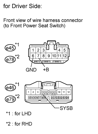
Disconnect the e45*1, e46*1, e78*2 and e79*2 switch connectors.
-
Measure the voltage according to the value(s) in the table below.
Standard voltage for LHD Tester Connection Condition Specified Condition e45-7 (+B) - Body ground Always 11 to 14 V e46-4 (SYSB) - Body ground Always 11 to 14 V for RHD Tester Connection Condition Specified Condition e78-7 (+B) - Body ground Always 11 to 14 V e79-4 (SYSB) - Body ground Always 11 to 14 V -
Measure the resistance according to the value(s) in the table below.
Standard resistance for LHD Tester Connection Condition Specified Condition e45-6 (GND) - Body ground Always Below 1 Ω for RHD Tester Connection Condition Specified Condition e78-6 (GND) - Body ground Always Below 1 Ω
-
-
for Passenger side:
-
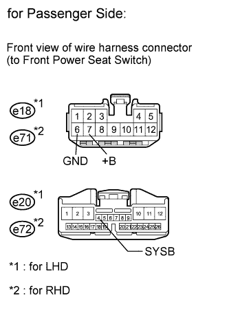
Disconnect the e18*1, e20*1, e71*2 and e72*2 switch connectors.
-
Measure the voltage according to the value(s) in the table below.
Standard voltage for LHD Tester Connection Condition Specified Condition e18-7 (+B) - Body ground Always 11 to 14 V e20-4 (SYSB) - Body ground Always 11 to 14 V for RHD Tester Connection Condition Specified Condition e71-7 (+B) - Body ground Always 11 to 14 V e72-4 (SYSB) - Body ground Always 11 to 14 V -
Measure the resistance according to the value(s) in the table below.
Standard resistance for LHD Tester Connection Condition Specified Condition e18-6 (GND) - Body ground Always Below 1 Ω for RHD Tester Connection Condition Specified Condition e71-6 (GND) - Body ground Always Below 1 Ω
-
NG
REPAIR OR REPLACE HARNESS OR CONNECTOR
OK 
REPLACE FRONT POWER SEAT SWITCH Click here
-