OUTER MIRROR SWITCH INSTALLATION

Tech Tips
A bolt without a torque specification is shown in the standard bolt chart Click here.
-
INSTALL OUTER MIRROR SWITCH ASSEMBLY
-
Attach the 4 claws to install the outer mirror switch assembly.
-
-
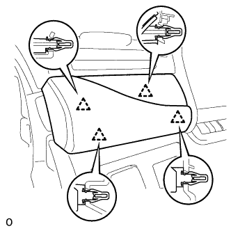
INSTALL NO. 1 INSTRUMENT PANEL SAFETY PAD SUB-ASSEMBLY
-
Connect each connector.
-
Attach the 5 clips and claw to install the No. 1 instrument panel safety pad sub-assembly.
-
Install the screw <C> and bolt.
-
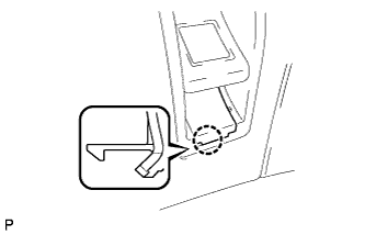
Attach the claw to install the switch base hole cover to the No. 1 instrument panel safety pad sub-assembly.
-
-
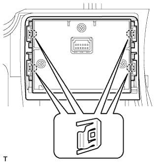
INSTALL INSTRUMENT PANEL ORNAMENT
-
Connect the connector.
-
Attach the 4 clips to install the instrument panel ornament.
-
-
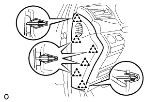
INSTALL INSTRUMENT SIDE PANEL LH
-
Attach the 6 clips to install the instrument side panel LH.
-