WINDSHIELD GLASS INSTALLATION

Tech Tips
-
Use the same procedures for the LHD and RHD.
-
The procedures listed below are for the LHD.
-
A bolt without a torque specification is shown in the standard bolt chart Click here.
-
INSTALL NO. 1 WINDSHIELD GLASS STOPPER
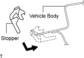
-
Install 2 new stoppers to the vehicle body as shown in the illustration.
-
-
INSTALL NO. 2 WINDSHIELD GLASS STOPPER
-
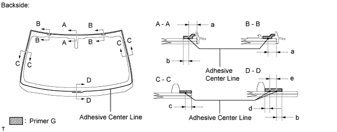
Apply Primer G to the glass where the stopper will be installed.
Note
-
Allow the primer to dry for 3 minutes or more.
-
Throw away any leftover primer.
-
Do not apply too much primer.
-
-
Install 2 new stoppers onto the glass as shown in the illustration.
-
-
INSTALL WINDSHIELD OUTSIDE MOULDING UPPER
-
Using a brush or sponge, coat the contact surface of the glass and moulding with Primer G.
Note
-
Allow the primer coating to dry for 3 minutes or more.
-
Do not coat the adhesive with Primer G.
-
Throw away any leftover primer.
-
Make sure the primer does not seep out on the vehicle outer side.
-
-
Install the windshield outside moulding, as shown in the illustration.
Note
Make sure the glass and moulding are flush.
-
-
INSTALL WINDSHIELD GLASS RETAINER
-
Apply Primer G to the glass where the retainer will be installed.
Note
-
Allow the primer to dry for 3 minutes or more.
-
Throw away any leftover primer.
-
Do not apply too much primer.
-
-
Install 2 new retainers onto the glass as shown in the illustration.
Specification Area Measurement a 30.0 mm (1.181 in.)
-
-
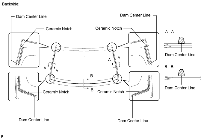
INSTALL WINDSHIELD GLASS ADHESIVE DAM
-
Apply Primer G to the glass where the glass adhesive dams will be installed.
Note
-
Allow the primer to dry for 3 minutes or more.
-
Throw away any leftover primer.
-
Do not apply too much primer.
-
-
Remove the peeling paper from the adhesive part of the dam. Install the dam (adhesive side) to the glass (Primer G area), but exclude the area above the notches on the upper part of the glass.
-
-
INSTALL WINDSHIELD GLASS SEAL
-
Remove the peeling paper from the windshield glass seal. Install the seal to the glass.
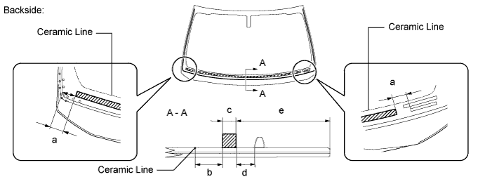
Specification Area Measurement a 30.0 mm (1.181 in.) b 20.0 mm (0.787 in.) c 10.0 mm (0.394 in.) d 13.0 mm (0.512 in.) e 88.7 mm (3.492 in.)
-
-
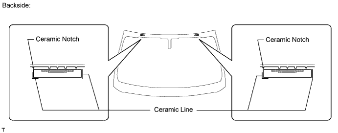
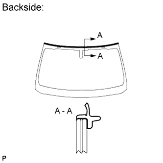
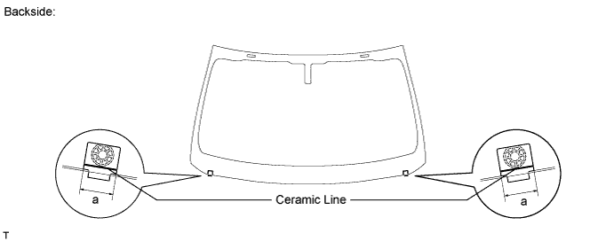
INSTALL WINDSHIELD GLASS
-
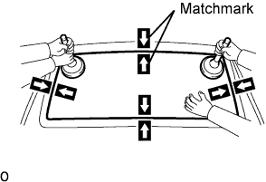
Position the glass.
-
Using suction cups, place the glass in the correct position.
-
Check that the entire contact surface of the glass rim is perfectly even.
-
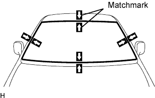
Place matchmarks on the glass and vehicle body on the locations indicated in the illustration.
Tech Tips
-
Placing matchmarks is only necessary when installing new glass. If it is the reused glass, matchmarks should already be present.
-
When reusing the glass, check and correct the matchmark positions.
Note
Check that the stoppers are attached to the vehicle body correctly.
-
-
Using suction cups, remove the glass.
-
-
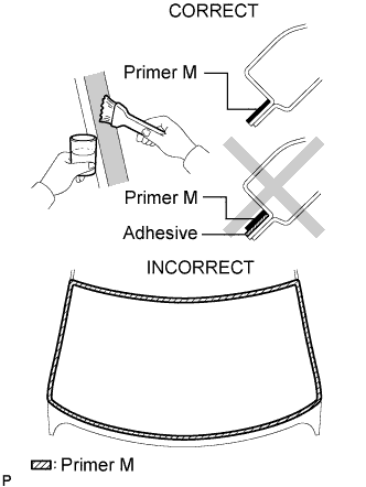
Using a brush, apply Primer M to the exposed part of the vehicle body.
Note
-
Allow the primer to dry for 3 minutes or more.
-
Do not apply primer to the adhesive.
-
Throw away any leftover primer.
-
Do not apply too much primer.
-
-
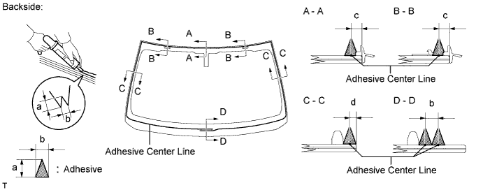
Using a brush or sponge, apply Primer G to the contact surface of the glass.
Specification Area Measurement a 6.5 mm (0.258 in.) b 7.0 mm (0.276 in.) c 3.0 mm (0.118 in.) d 4.0 mm (0.157 in.) e 8.0 mm (0.315 in.) Tech Tips
If the primer is applied to an area that is not specified, apply non-residue solvent to a clean cloth and wipe off the excess primer before it dries.
Note
-
Allow the primer to dry for 3 minutes or more.
-
Throw away any leftover primer.
-
Do not apply too much primer.
-
-
Apply adhesive to the glass.
Adhesive Toyota Genuine Windshield Glass Adhesive or equivalent
-
Cut off the tip of the cartridge nozzle as shown in the illustration.
Tech Tips
After cutting off the tip, use all adhesive within the time written in the table below.
Usage timeframe Temperature Usage Timeframe 35°C (95°F) 15 minutes 20°C (68°F) 1 hour 40 minutes 5°C (41°F) 8 hours -
Load the sealer gun with the cartridge.
-
Apply adhesive to the glass as shown in the illustration.
Specification Area Measurement a 12.0 mm (0.472 in.) b 8.0 mm (0.315 in.) c 6.5 mm (0.258 in.) d 3.0 mm (0.118 in.)
-
-
Install the glass to the vehicle body.
-
Using suction cups, position the glass so that the matchmarks are aligned. Press it in gently along the rim.
-
Lightly press the outer surface of the glass to ensure that it is securely fit to the vehicle body.
Note
-
Check that the stoppers are attached to the vehicle body correctly.
-
Check that the vehicle body and glass have a small gap between them.
-
-
Hold the glass in place securely with protective tape or equivalent until the adhesive hardens.
Note
Do not drive the vehicle for the amount of time written in the table below.
Minimum time Temperature Minimum time prior to driving vehicle 35°C (95°F) 1 hour 30 minutes 20°C (68°F) 5 hours 5°C (41°F) 24 hours
-
-
w/ Windshield Deicer System:
Connect the windshield deicer connector.
-
-
CHECK FOR LEAKS AND REPAIR
-
Conduct a leak test after the adhesive has completely hardened.
-
Seal any leaks with auto glass sealer.
-
-
INSTALL ROOF HEADLINING
-
Return the roof headlining to its original position.
for Standard Body, refer to the following procedures ( Click here).
for Long Body, refer to the following procedures ( Click here).
-
-
INSTALL RAIN SENSOR
-
If reusing the rain sensor:
Install new rain sensor tape.
-
Remove the used rain sensor tape from the windshield glass or rain sensor.
-
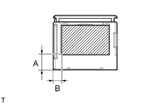
Apply new rain sensor tape on the rain sensor lens surface indicated by the hatched area.
Note
-
Keep the tape's exposed adhesive free from dust and fingerprints.
-
Apply the tape exactly according to the specifications below.
Specification Area Measurement A 15.0 mm (0.591 in.) B 8.0 mm (0.315 in.)
-
-
-
-
INSTALL RAIN SENSOR
Note
-
Make sure the adhesive between the bracket and windshield glass is normal.
-
If there is any residue left from the rain sensor tape on the windshield, remove it.
-
Clean the glass surface with a cloth or similar material.
-
Make sure there are no air bubbles between the rain sensor and windshield.
-
Peel the peeling paper from the rain sensor tape.
-
Securely attach the rain sensor to the bracket.
-
Push the stopper upward.
-
Connect the connector.
-
-
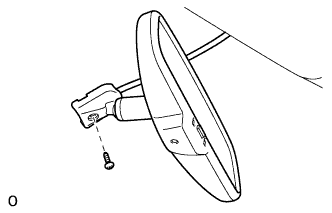
INSTALL INNER REAR VIEW MIRROR ASSEMBLY (w/o Automatic High Beam System)
-
Using a T20 "TORX" socket wrench, install the inner rear view mirror with the screw.
- Torque:
- 1.8 N*m { 18 kgf*cm, 16 in.*lbf }
-
Connect the connector.
-
-
REMOVE INNER REAR VIEW MIRROR ASSEMBLY (w/ Automatic High Beam System)
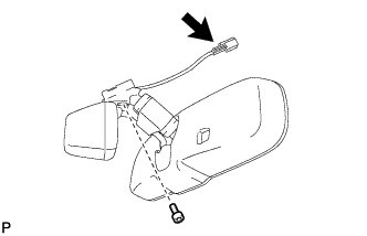
Note
-
Do not touch the camera lens (built into the inner rear view mirror assembly) with a bare hand.
-
Do not allow anything to adhere to the camera lens (built into the inner rear view mirror assembly).
-
Do not apply strong impacts to the inner rear view mirror assembly.
-
Do not allow any liquid to get on the inner rear view mirror assembly.
-
Using a T20 "TORX" socket wrench, install the inner rear view mirror with the screw.
- Torque:
- 1.5 N*m { 15 kgf*cm, 13 in.*lbf }
-
Connect the connector.
-
-
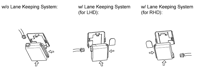
INSTALL RAIN SENSOR COVER (w/o Lane Keeping Assist System)
-

Attach the 2 claws to install the rain sensor cover.
-
Push the stopper as shown in the illustration to fix the cover in place.
-
-
INSTALL RAIN SENSOR COVER (w/ Lane Keeping Assist System)
Note
When removing and installing the rain sensor cover, do not apply force to the object recognition camera areas labeled "X".
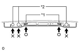
Text in Illustration *1 Clip *2 Camera
-
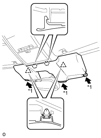
While being careful not to apply force to the camera area, attach the 2 claws and 2 clips to install the rain sensor cover.
-
Push the stopper as shown in the illustration to fix the cover in place.
Text in Illustration *1 Stopper
-
-
INSTALL MAP LIGHT ASSEMBLY
-
Connect the connectors.
-
Attach the 2 clips to install the map light assembly.
-
Install the 2 screws.
-
Attach the 2 claws and 2 covers.
-
-
INSTALL ASSIST GRIP SUB-ASSEMBLY
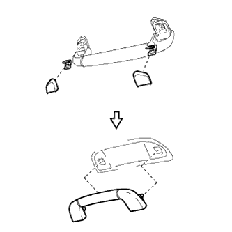
Tech Tips
Use the same procedure for all the assist grips.
-
Assemble the assist grip sub-assembly, 2 clips and 2 covers as shown in the illustration.
-
Attach the 2 clips to install the assist grip sub-assembly.
-
-
INSTALL VISOR HOLDER
Tech Tips
Use the same procedure to install the visor holder on the other side.
-
Attach the 2 claws to install the visor holder.
-
Push in the visor holder and turn it approximately 45° as shown in the illustration.
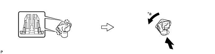
Text in Illustration *a 45° - -
-
-
INSTALL VISOR ASSEMBLY LH
-
Install the visor assembly with the 2 screws.
-
-
INSTALL VISOR ASSEMBLY RH
Tech Tips
Use the same procedure described for the LH side.
-
INSTALL VISOR BRACKET COVER
Tech Tips
Use the same procedure to install the cover on the other side.
-
Attach the 4 claws to install the visor bracket cover.
-
-
INSTALL FRONT PILLAR GARNISH LH
-
Attach the guide.
-
Turn the end of the front pillar garnish clip 90° with needle-nose pliers and install it to the front pillar garnish LH.
Tech Tips
Tape the tips of the needle-nose pliers before use.
Text in Illustration *1 Front Pillar Garnish Clip *2 Protective Tape -
Attach the 2 clips to install the front pillar garnish LH.
Note
After installing the front pillar garnish LH, make sure that the lip of the front door opening trim weatherstrip LH is not pinched.
-
-
INSTALL FRONT PILLAR GARNISH RH
Tech Tips
Use the same procedure described for the LH side.
-
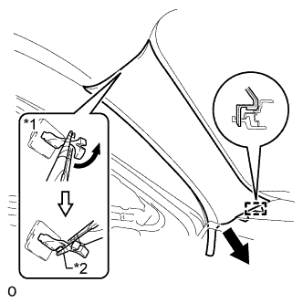
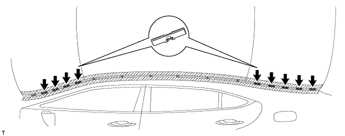
INSTALL ROOF NO. 1 DRIP SIDE FINISH MOULDING CLIP
Tech Tips
Perform the following procedure if replacing the No. 1 roof drip side finish moulding clip.
Note
Remove the double-sided tape remaining where the clips will be installed on the body and clean the body with a non-residue type solvent.
-
Text in Illustration *1 Adhesive *a 2 to 3 mm Bead of Adhesive Apply a 2 to 3 mm (0.07 to 0.11 in.) bead of adhesive (3M DP-105 or equivalent) to new No. 1 roof drip side finish moulding clips.
Tech Tips
Adhesive strength (tensile strength): 13.7 MPa (140 kgf/cm2, 1991 psi) or more {when the temperature is 23°C (73°F)}
-
for Standard Body:
Press and install the 6 No. 1 roof drip side finish moulding clips.
-
for Long Body:
Press and install the 7 No. 1 roof drip side finish moulding clips.

-
Install the clips to the positions on the roof panel shown in the illustration. Determine the locations and firmly press and install the No. 1 roof drip side finish moulding clips after lightly applying adhesive (3M DP-105 or equivalent).
-
Install the roof drip side finish moulding center when 40 minutes or more have elapsed after pressing and installing the No. 1 roof drip side finish moulding clips.
Tech Tips
-
Initial hardening time: 40 minutes
-
Complete hardening time: 48 hours
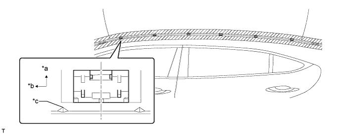
Text in Illustration *a Outside *b Front *c Location - -
-
-
-
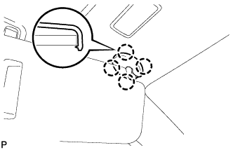
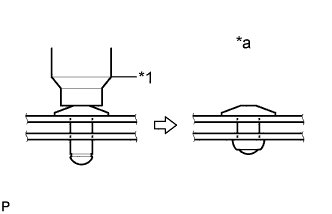
INSTALL NO. 3 WINDSHIELD OUTSIDE MOULDING CLIP
Tech Tips
Perform the following procedure if replacing the No. 3 windshield outside moulding clip.
-
Using an air riveter or hand riveter with a nose piece, install the 10 new rivets.
Tech Tips
If the rivet cannot be cut, pull it once and cut it.
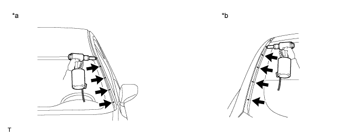
Text in Illustration *a Front Side *b Rear Side Note
-
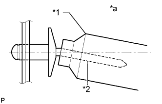
Do not pry the rivet with the riveter, as this will cause damage to the riveter and mandrel.
Text in Illustration *1 Riveter *2 Mandrel *a INCORRECT -
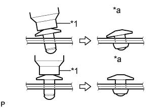
Confirm that the rivets are seated properly against the moulding.
Text in Illustration *1 Riveter *a INCORRECT -
Do not tilt the riveter when installing the rivet to the moulding.
-
Do not leave any space between the rivet head and moulding.
-
Do not leave any space between the moulding and door frame. Firmly hold together the 2 items while installing the rivet.
Text in Illustration *1 Riveter *a INCORRECT
-
-
-
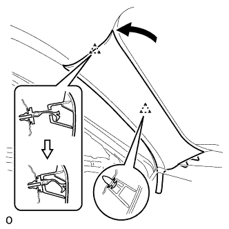
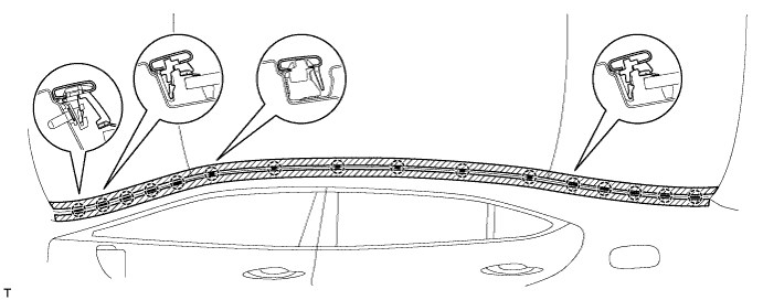
INSTALL ROOF NO. 2 DRIP SIDE FINISH MOULDING CLIP
Tech Tips
Perform the following procedure if replacing the No. 2 roof drip side finish moulding clips.
-
Install the 9 No. 2 moulding clips.
-
-
INSTALL NO. 2 WINDSHIELD OUTSIDE MOULDING CLIP
Tech Tips
Perform the following procedure if replacing the No. 2 windshield outside moulding clip.
-

Install the No. 2 moulding clip.
-
-
INSTALL NO. 1 WINDSHIELD OUTSIDE MOULDING CLIP
Tech Tips
Use the same procedures described for the No. 2 windshield outside moulding clip.
-
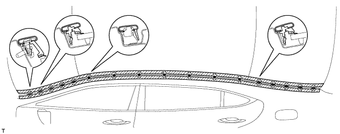
INSTALL ROOF DRIP SIDE FINISH MOULDING CENTER LH
-
for Standard Body:
Attach the 16 clips to install the moulding.
-
for Long Body:
Attach the 17 clips to install the moulding.
-
Remove the protective tape from the edges of the moulding.
-
-
INSTALL ROOF DRIP SIDE FINISH MOULDING CENTER RH
Tech Tips
Use the same procedure described for the LH side.
-
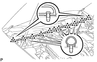
INSTALL COWL TOP VENTILATOR LOUVER SUB-ASSEMBLY
-
Push the ventilator louver in the direction indicated by the arrow in the illustration to attach the 9 claws and 2 clips and install the ventilator louver.
-
-
INSTALL COWL TOP VENTILATOR LOUVER PROTECTOR LH
-
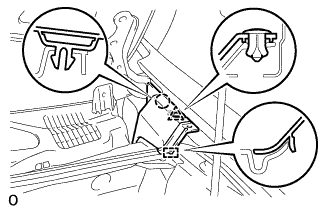
Attach the claw and guide to install the cowl top ventilator louver protector LH.
-
Attach the clip.
-
-
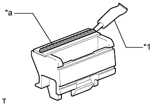
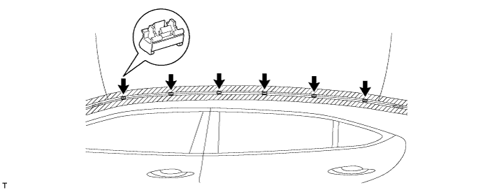
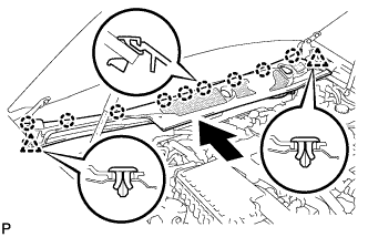
INSTALL HOOD TO COWL TOP SEAL
-
Attach the 11 clips and install the cowl top seal.
-
-
INSTALL FRONT FENDER TO COWL SIDE SEAL LH
-

Attach the claw and clip to install the front fender to cowl side seal LH.
-
-
INSTALL FRONT FENDER TO COWL SIDE SEAL RH
Tech Tips
Use the same procedure described for the LH side.
-
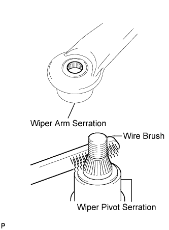
INSTALL FRONT WIPER ARM LH
-
Stop the wiper motor at the automatic stop position.
-
Clean the wiper arm serration with a round file or equivalent.
-
Clean the wiper pivot serration with a wire brush.
-
Install the wiper arm and blade with the nut. Make sure that the wiper arm and blade comes to the position shown in the illustration.
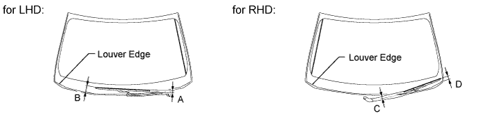
Standard measurement Position Specified Condition A 16.3 mm (0.646 in.) B 61.7 to 76.7 mm (2.429 to 3.020 in.) C 23.2 mm (0.913 in.) D 35.6 to 50.6 mm (1.401 to 1.992 in.) - Torque:
- 22 N*m { 224 kgf*cm, 16 ft.*lbf }
Tech Tips
Hold down the wiper arm hinge with your hand while tightening the nut.
-
-
INSTALL FRONT WIPER ARM RH
-
Stop the wiper motor at the automatic stop position.
-
Clean the wiper arm serration with a round file or equivalent.
-
Clean the wiper pivot serration with a wire brush.
-
Install the wiper arm and blade with the nut. Make sure that the wiper arm and blade comes to the position shown in the illustration.
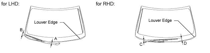
Standard measurement Position Specified Condition A 23.2 mm (0.913 in.) B 35.6 to 50.6 mm (1.401 to 1.992 in.) C 16.3 mm (0.646 in.) D 61.7 to 76.7 mm (2.429 to 3.020 in.) - Torque:
- 22 N*m { 224 kgf*cm, 16 ft.*lbf }
Tech Tips
Hold down the wiper arm hinge with your hand while tightening the nut.
-
Operate the front wipers while spraying washer fluid on the windshield glass. Make sure that the front wipers function properly and there is no interference with the vehicle body.
-
-
CONNECT CABLE TO NEGATIVE BATTERY TERMINAL
Note
When disconnecting the cable, some systems need to be initialized after the cable is reconnected Click here.
-
INSTALL COWL TOP VENTILATOR LOUVER RH
-

for LHD:
Install the 6 clips and cowl top ventilator louver RH.
Note
If the cowl top ventilator louver RH is not properly installed, water may leak into the engine room and cause malfunctions. Therefore, make sure the cowl top ventilator louver RH is installed properly.
-

for RHD:
Install the 6 clips and cowl top ventilator louver LH.
Note
If the cowl top ventilator louver LH is not properly installed, water may leak into the engine room and cause malfunctions. Therefore, make sure the cowl top ventilator louver LH is installed properly.
-
-
ADJUST ADAPTIVE HIGH BEAM CAMERA BEAM AXIS