POWER WINDOW REGULATOR MOTOR (for Front Door) INSTALLATION

Tech Tips
-
Use the same procedures for the LH side and RH side.
-
The procedures listed below are for the LH side.
-
INSTALL FRONT POWER WINDOW REGULATOR MOTOR ASSEMBLY LH
-
Apply MP grease to the sliding and rotating areas of the power window regulator motor assembly LH.
-
Using a T25 ''TORX'' driver, install the power window regulator motor assembly LH with the 3 screws.
- Torque:
- 5.4 N*m { 55 kgf*cm, 48 in.*lbf }
-
-
INSTALL FRONT DOOR WINDOW REGULATOR SUB-ASSEMBLY LH
-
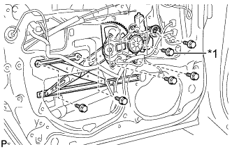
Text in Illustration *1 Temporary Bolt Apply MP grease to the sliding and rotating area of the front door window regulator sub-assembly LH.
Note
Do not apply grease to the spring of the window regulator.
-
Temporarily install the temporary bolt to the front door window regulator sub-assembly LH.
-
Install the window regulator with the 5 bolts and tighten the temporary bolt.
- Torque:
- 11 N*m { 112 kgf*cm, 8 ft.*lbf }
Note
Be careful not to drop the window regulator as it may become damaged.
-
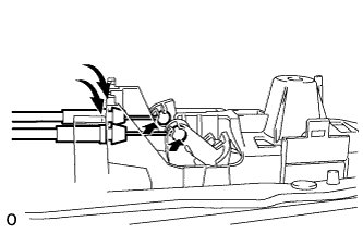
Connect the connector.
-
-
INSTALL FRONT DOOR GLASS SUB-ASSEMBLY LH
-
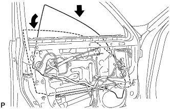
Insert the front door glass sub-assembly LH into the door panel along the glass run as indicated by the arrows in the illustration.
Note
Be careful not to damage the glass.
-
Install the front door glass sub-assembly LH to the front door window regulator sub-assembly LH with the 2 bolts.
- Torque:
- 5.5 N*m { 56 kgf*cm, 49 in.*lbf }
-
Install the hole plug.
-
-
INSTALL FRONT DOOR SERVICE HOLE COVER LH
-
Apply new butyl tape to the door.
-
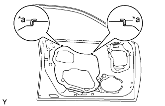
Text in Illustration *a Reference Point Install a new front door service hole cover LH using the reference points on the front door panel.
Tech Tips
-
When installing the service hole cover, pull the links and connectors through the service hole cover.
-
There should be no wrinkles or folds after attaching the service hole cover.
-
After attaching the service hole cover, check the sealing quality.
-
-
-
INSTALL DOOR FRAME GARNISH LH
-
Install the door frame garnish LH with the 2 clips.
-
-
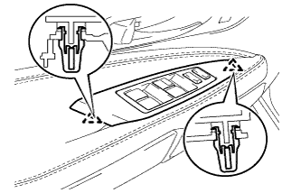
INSTALL FRONT DOOR TRIM COVER LH
-
Attach the 5 clips to install the front door trim cover LH.
-
Install the cushion.
-
-
INSTALL COURTESY LIGHT ASSEMBLY
-
Attach the claw to install the courtesy light assembly.
-
Connect the connector.
-
-
INSTALL FRONT DOOR INSIDE HANDLE ILLUMINATION LIGHT ASSEMBLY LH
-
Connect the connector.
-
Attach the claw to install the front door inside handle illumination light assembly LH.
-
-
INSTALL FRONT DOOR TRIM BOARD SUB-ASSEMBLY LH
-
Connect the connector.
-
Connect the 2 cables to the inside handle.
-
Attach the 13 clips to install the front door trim board sub-assembly LH.
-
Install the 3 screws.
-
-
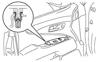
INSTALL POWER WINDOW REGULATOR MASTER SWITCH ASSEMBLY WITH FRONT DOOR ARMREST BASE PANEL
-
Connect the connector.
-
Install the multiplex network master switch assembly.
-
-
INSTALL POWER WINDOW REGULATOR SWITCH ASSEMBLY WITH FRONT DOOR ARMREST BASE PANEL (for RHD)
-
Connect the 2 connectors.
-
Install the front power window regulator switch assembly.
-
-
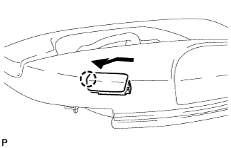
INSTALL DOOR INSIDE HANDLE BEZEL PLUG
-
Attach the 3 claws to install the front door inside handle bezel plug LH.
-
-
CONNECT CABLE TO NEGATIVE BATTERY TERMINAL
Note
When disconnecting the cable, some systems need to be initialized after the cable is reconnected Click here.