POWER WINDOW CONTROL SYSTEM Driver Side Power Window does not Operate with Power Window Master Switch
DESCRIPTION
-
If the manual UP/DOWN function does not operate, there may be a malfunction in the master switch, power window regulator motor or wire harness.
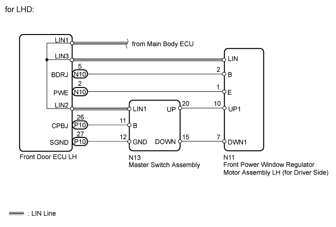
WIRING DIAGRAM

INSPECTION PROCEDURE
PROCEDURE
-
CHECK LIN COMMUNICATION SYSTEM
-
Check for LIN communication system DTCs related to the power window control system.
Result: Result Proceed to DTC is output A DTC is not output B
A 
GO TO LIN COMMUNICATION SYSTEM Click here
B 
-
-
CHECK FOR DTC (B2312)
-
Check if DTC B2312 is output.
Result: Result Proceed to DTC is output A DTC is not output B
A
GO TO DTC B2312 Click here
B
-
-
READ VALUE USING INTELLIGENT TESTER (DRIVER SIDE MOTOR)
-
Connect the intelligent tester to the DLC3.
-
Turn the engine switch on (IG).
-
Turn ON the intelligent tester.
-
Enter the following menus.
-
Select: Body / D-Door Motor / Data List /
-
-
According to the display on tester, read the "Data List".
D-Door Motor: Tester Display Measurement Item/Range Normal Condition Diagnostic Note D Door P/W Up SW Driver side power window MANUAL UP switch signal / ON or OFF ON: Driver side power window manual UP switch on master switch operated
OFF: Driver side power window switch on master switch not operated
- D Door P/W Down SW Driver side power window MANUAL DOWN switch signal / ON or OFF ON: Driver side power window manual DOWN switch on master switch operated
OFF: Driver side power window switch on master switch not operated
- OK Tester display changes normally when master switch is operated.
OK 
INSPECT FRONT POWER WINDOW REGULATOR MOTOR ASSEMBLY Click here
NG
-
-
CHECK HARNESS AND CONNECTOR (MASTER SWITCH - DRIVER SIDE DOOR ECU)
-
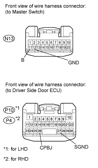
Disconnect the N13 switch connector.
-
Disconnect the P10*1 or P4*2 ECU connector.
-
Measure the resistance according to the value(s) in the table below.
Standard resistance for LHD: Tester Connection Condition Specified Condition P10-27 (SGND) - N13-12 (GND) Always Below 1 Ω P10-26 (CPBJ) - N13-11 (B) Always Below 1 Ω P10-27 (SGND) or N13-12 (GND) - Body ground Always 10 kΩ or higher P10-26 (CPBJ) or N13-11 (B) - Body ground Always 10 kΩ or higher for RHD: Tester Connection Condition Specified Condition P4-27 (SGND) - N13-12 (GND) Always Below 1 Ω P4-26 (CPBJ) - N13-11 (B) Always Below 1 Ω P4-27 (SGND) or N13-12 (GND) - Body ground Always 10 kΩ or higher P4-26 (CPBJ) or N13-11 (B) - Body ground Always 10 kΩ or higher
NG
REPAIR OR REPLACE HARNESS OR CONNECTOR
OK
-
-
CHECK HARNESS AND CONNECTOR (DRIVER SIDE DOOR ECU - DRIVER SIDE MOTOR)
-
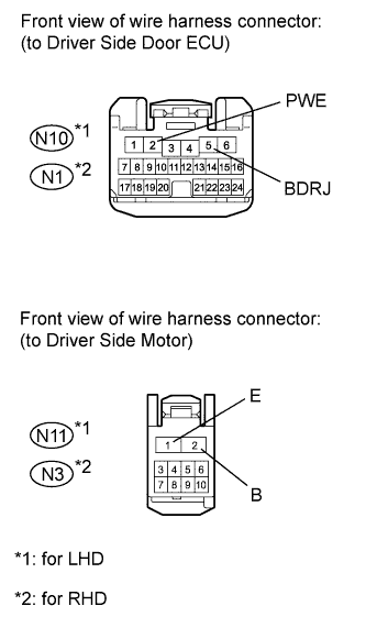
Disconnect the N10*1 or N1*2 ECU connector.
-
Disconnect the N11*1 or N3*2 motor connector.
-
Measure the resistance according to the value(s) in the table below.
Standard resistance for LHD: Tester Connection Condition Specified Condition N10-5 (BDRJ) - N11-2 (B) Always Below 1 Ω N10-2 (PWE) - N11-1 (E) Always Below 1 Ω N10-5 (BDRJ) or N11-2 (B) - Body ground Always 10 kΩ or higher N10-2 (PWE) or N11-1 (E) - Body ground Always 10 kΩ or higher for RHD: Tester Connection Condition Specified Condition N1-5 (BDRJ) - N3-2 (B) Always Below 1 Ω N1-2 (PWE) - N3-1 (E) Always Below 1 Ω N1-5 (BDRJ) or N3-2 (B) - Body ground Always 10 kΩ or higher N1-2 (PWE) or N3-1 (E) - Body ground Always 10 kΩ or higher
NG
REPAIR OR REPLACE HARNESS OR CONNECTOR
OK
-
-
CHECK HARNESS AND CONNECTOR (DRIVER SIDE MOTOR - MASTER SWITCH)
-
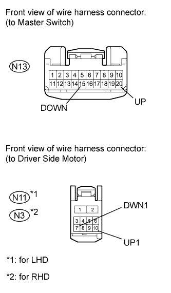
Disconnect the N13 switch connector.
-
Disconnect the N11*1 or N3*2 motor connector.
-
Measure the resistance according to the value(s) in the table below.
Standard resistance for LHD: Tester Connection Condition Specified Condition N13-20 (UP) - N11-10 (UP1) Always Below 1 Ω N13-15 (DOWN) - N11-7 (DWN1) Always Below 1 Ω N13-20 (UP) or N11-10 (UP1) - Body ground Always 10 kΩ or higher N13-15 (DOWN) or N11-7 (DWN1) - Body ground Always 10 kΩ or higher for RHD: Tester Connection Condition Specified Condition N13-20 (UP) - N3-10 (UP1) Always Below 1 Ω N13-15 (DOWN) - N3-7 (DWN1) Always Below 1 Ω N13-20 (UP) or N3-10 (UP1) - Body ground Always 10 kΩ or higher N13-15 (DOWN) or N3-7 (DWN1) - Body ground Always 10 kΩ or higher
NG
REPAIR OR REPLACE HARNESS OR CONNECTOR
OK
-
-
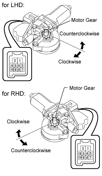
INSPECT FRONT POWER WINDOW REGULATOR MOTOR ASSEMBLY
-
Remove the motor.
-
Apply positive (+) battery voltage to the connector terminal 2.
Note
-
Do not apply positive (+) battery voltage to any terminals, except terminal 2, to avoid damaging the pulse sensor inside the motor.
-
Reset the power window regulator motor (initialize the pulse sensor) after installing the power window regulator motor and regulator assembly onto the door.
-
-
Apply negative (-) battery voltage to the connector terminals 1 and 7 / 10.
-
Check that the motor gear rotates smoothly as follows.
OK for LHD: Measurement Condition Specified Condition Battery positive (+) → 2
Battery negative (-):
1 (3 seconds or more) → 1 and 10 (within 1 second) → 1 (within 1 second) → 1 and 10
Motor gear rotates clockwise (UP) Battery positive (+) → 2
Battery negative (-):
1 (3 seconds or more) → 1 and 7 (within 1 second) → 1 (within 1 second) → 1 and 7
Motor gear rotates counterclockwise (DOWN) for RHD: Measurement Condition Specified Condition Battery positive (+) → 2
Battery negative (-):
1 (3 seconds or more) → 1 and 10 (within 1 second) → 1 (within 1 second) → 1 and 10
Motor gear rotates counterclockwise (UP) Battery positive (+) → 2
Battery negative (-):
1 (3 seconds or more) → 1 and 7 (within 1 second) → 1 (within 1 second) → 1 and 7
Motor gear rotates clockwise (DOWN) Result: Result Proceed to OK A NG (for LHD) B NG (for RHD) C
B
REPLACE FRONT POWER WINDOW REGULATOR MOTOR ASSEMBLY LH Click here
C
REPLACE FRONT POWER WINDOW REGULATOR MOTOR ASSEMBLY RH Click here
A 
REPLACE MASTER SWITCH ASSEMBLY Click here
-