POWER WINDOW CONTROL SYSTEM, Diagnostic DTC:B2312

| DTC Code | DTC Name |
|---|---|
| B2312 | Power Window Switch Malfunction |
DESCRIPTION
The power window regulator motor assembly consists of the motor, regulator and ECU. The power window regulator motor assembly is driven by operating the power window regulator switch. This DTC is output when the ECU built into the regulator motor determines that the power window switch is stuck.
Tech Tips
This DTC may occur for all the windows.
Note
-
When the power window regulator motor is reinstalled or replaced, the power window control system must be initialized.
-
After a door glass or a door glass run has been replaced, the jam protection function may operate unexpectedly when the AUTO UP function is used. In such cases, the AUTO UP function can be resumed by repeating the following operation at least 5 times:
-
Close the power window by fully pulling up the power window switch and holding it in the AUTO UP position.
-
Open the power window by fully pushing down the switch.
| DTC Code | DTC Detection Condition | Trouble Area |
|---|---|---|
| B2312 | Master switch stuck |
|
| DTC Code | DTC Detection Condition | Trouble Area |
|---|---|---|
| B2312 | Master switch stuck |
|
| DTC Code | DTC Detection Condition | Trouble Area |
|---|---|---|
| B2312 | Power window regulator switch stuck |
|
| DTC Code | DTC Detection Condition | Trouble Area |
|---|---|---|
| B2312 | Power window regulator switch stuck |
|
| DTC Code | DTC Detection Condition | Trouble Area |
|---|---|---|
| B2312 | Power window regulator switch stuck |
|
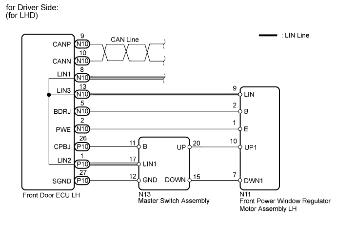
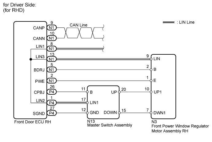
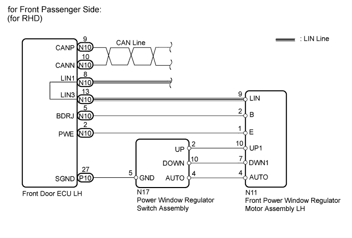
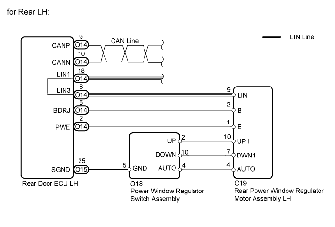
WIRING DIAGRAM


INSPECTION PROCEDURE
PROCEDURE
-
CHECK LIN COMMUNICATION SYSTEM
-
Check for LIN communication system DTCs related to the power window control system.
Result: Result Proceed to DTC is output A DTC is not output B
A 
GO TO LIN COMMUNICATION SYSTEM Click here
B 
-
-
CHECK CAN COMMUNICATION SYSTEM
-
Check for CAN communication system DTCs related to the power window control system.
Result: Result Proceed to DTC is output (for LHD) A DTC is output (for RHD) B DTC is not output C
A
GO TO CAN COMMUNICATION SYSTEM (for LHD) Click here
B
GO TO CAN COMMUNICATION SYSTEM (for RHD) Click here
C
-
-
CHECK FOR DTC
-
Check where DTC B2312 is output from.
Result: Result Proceed to B2312 output from Master switch A B2312 output from driver side motor B B2312 output from front passenger side motor C B2312 output from rear motor LH D B2312 output from rear motor RH E
B 
READ VALUE USING INTELLIGENT TESTER (DRIVER SIDE MOTOR) Click here
C
READ VALUE USING INTELLIGENT TESTER (FRONT PASSENGER SIDE MOTOR) Click here
D
READ VALUE USING INTELLIGENT TESTER (REAR MOTOR LH) Click here
E
READ VALUE USING INTELLIGENT TESTER (REAR MOTOR RH) Click here
A
-
-
READ VALUE USING INTELLIGENT TESTER (MASTER SWITCH)
-
Connect the intelligent tester to the DLC3.
-
Turn the engine switch on (IG).
-
Turn ON the intelligent tester.
-
Enter the following menus.
-
Select: Body / Master Switch / Data List /
-
-
According to the display on tester, read the "Data List".
Master switch: Tester Display Measurement Item/Range Normal Condition Diagnostic Note D Door P/W Auto SW Driver side power window auto UP/DOWN switch signal / ON or OFF ON: Driver side power window auto UP/DOWN switch on master switch operated
OFF: Driver side power window switch on master switch not operated
- P Door P/W Auto SW Front passenger side power window remote auto UP/DOWN switch signal / ON or OFF ON: Front passenger side power window remote auto UP/DOWN switch on master switch operated
OFF: Front passenger side power window switch on master switch not operated
- RR Door P/W Auto SW Rear power window RH remote auto UP/DOWN switch signal / ON or OFF ON: Rear power window RH remote auto UP/DOWN switch on master switch operated
OFF: Rear power window RH switch on master switch not operated
- RL Door P/W Auto SW Rear power window LH remote auto UP/DOWN switch signal / ON or OFF ON: Rear power window LH remote auto UP/DOWN switch on master switch operated
OFF: Rear power window LH switch on master switch not operated
- P Door P/W Up SW Front passenger side power window remote manual UP switch signal / ON or OFF ON: Front passenger side power window remote manual UP switch on master switch operated
OFF: Front passenger side power window switch on master switch not operated
- RR Door P/W Up Switch Rear power window RH remote manual UP switch signal / ON or OFF ON: Rear power window RH remote manual UP switch on master switch operated
OFF: Rear power window RH switch on master switch not operated
- RL Door P/W Up Switch Rear power window LH remote manual UP switch signal / ON or OFF ON: Rear power window LH remote manual UP switch on master switch operated
OFF: Rear power window LH switch on master switch not operated
- P Door P/W Down SW Front passenger side power window remote manual DOWN switch signal / ON or OFF ON: Front passenger side power window remote manual DOWN switch on master switch operated
OFF: Front passenger side power window switch on master switch not operated
- RR Door P/W Down SW Rear power window RH remote manual DOWN switch signal / ON or OFF ON: Rear power window RH remote manual DOWN switch on master switch operated
OFF: Rear power window RH switch on master switch not operated
- RL Door P/W Down SW Rear power window LH remote manual DOWN switch signal / ON or OFF ON: Rear power window LH remote manual DOWN switch on master switch operated
OFF: Rear power window LH switch on master switch not operated
- Window Lock Switch Status Power window LOCK switch / ON or OFF ON: Power window lock switch LOCK position
OFF: Power window lock switch UNLOCK position
- OK Tester display changes normally when master switch is operated.
NG
REPLACE MASTER SWITCH ASSEMBLY Click here
OK 
END (DUE TO KEEPING SWITCH OPERATED FOR 20 SECONDS OR MORE)
-
-
READ VALUE USING INTELLIGENT TESTER (DRIVER SIDE MOTOR)
-
Connect the intelligent tester to the DLC3.
-
Turn the engine switch on (IG).
-
Turn ON the intelligent tester.
-
Enter the following menus.
-
Select: Body / D-Door Motor / Data List /
-
-
According to the display on tester, read the "Data List".
D-Door Motor: Tester Display Measurement Item/Range Normal Condition Diagnostic Note D Door P/W Auto SW Driver side power window auto UP/DOWN switch signal / ON or OFF ON: Driver side power window auto UP/DOWN switch on master switch operated
OFF: Driver side power window switch on master switch not operated
- D Door P/W Up SW Driver side power window MANUAL UP switch signal / ON or OFF ON: Driver side power window manual UP switch on master switch operated
OFF: Driver side power window switch on master switch not operated
- D Door P/W Down SW Driver side power window MANUAL DOWN switch signal / ON or OFF ON: Driver side power window manual DOWN switch on master switch operated
OFF: Driver side power window switch on master switch not operated
- OK Tester display changes normally when master switch is operated.
NG
CHECK HARNESS AND CONNECTOR (MASTER SWITCH - DRIVER SIDE DOOR ECU) Click here
OK
END (DUE TO KEEPING SWITCH OPERATED FOR 20 SECONDS OR MORE)
-
-
CHECK HARNESS AND CONNECTOR (MASTER SWITCH - DRIVER SIDE DOOR ECU)
-
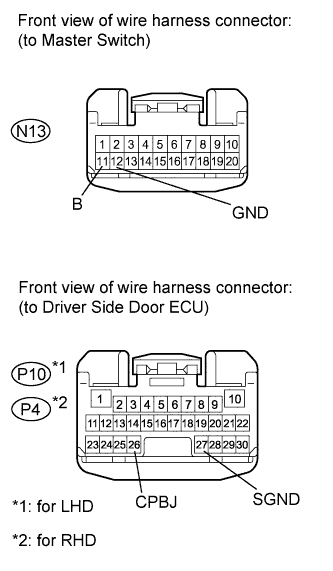
Disconnect the N13 switch connector.
-
Disconnect the P10*1 or P4*2 ECU connector.
-
Measure the resistance according to the value(s) in the table below.
Standard resistance for LHD: Tester Connection Condition Specified Condition P10-27 (SGND) - N13-12 (GND) Always Below 1 Ω P10-26 (CPBJ) - N13-11 (B) Always Below 1 Ω P10-27 (SGND) or N13-12 (GND) - Body ground Always 10 kΩ or higher P10-26 (CPBJ) or N13-11 (B) - Body ground Always 10 kΩ or higher for RHD: Tester Connection Condition Specified Condition P4-27 (SGND) - N13-12 (GND) Always Below 1 Ω P4-26 (CPBJ) - N13-11 (B) Always Below 1 Ω P4-27 (SGND) or N13-12 (GND) - Body ground Always 10 kΩ or higher P4-26 (CPBJ) or N13-11 (B) - Body ground Always 10 kΩ or higher
NG
REPAIR OR REPLACE HARNESS OR CONNECTOR
OK
-
-
CHECK HARNESS AND CONNECTOR (DRIVER SIDE DOOR ECU - DRIVER SIDE MOTOR)
-
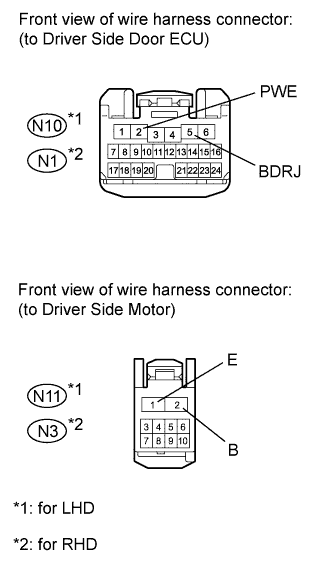
Disconnect the N10*1 or N1*2 ECU connector.
-
Disconnect the N11*1 or N3*2 motor connector.
-
Measure the resistance according to the value(s) in the table below.
Standard resistance for LHD: Tester Connection Condition Specified Condition N10-5 (BDRJ) - N11-2 (B) Always Below 1 Ω N10-2 (PWE) - N11-1 (E) Always Below 1 Ω N10-5 (BDRJ) or N11-2 (B) - Body ground Always 10 kΩ or higher N10-2 (PWE) or N11-1 (E) - Body ground Always 10 kΩ or higher for RHD: Tester Connection Condition Specified Condition N1-5 (BDRJ) - N3-2 (B) Always Below 1 Ω N1-2 (PWE) - N3-1 (E) Always Below 1 Ω N1-5 (BDRJ) or N3-2 (B) - Body ground Always 10 kΩ or higher N1-2 (PWE) or N3-1 (E) - Body ground Always 10 kΩ or higher
NG
REPAIR OR REPLACE HARNESS OR CONNECTOR
OK
-
-
CHECK HARNESS AND CONNECTOR (MASTER SWITCH - DRIVER SIDE MOTOR)
-
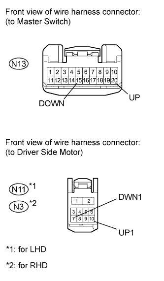
Disconnect the N13 switch connector.
-
Disconnect the N11*1 or N3*2 motor connector.
-
Measure the resistance according to the value(s) in the table below.
Standard resistance for LHD: Tester Connection Condition Specified Condition N13-20 (UP) - N11-10 (UP1) Always Below 1 Ω N13-15 (DOWN) - N11-7 (DWN1) Always Below 1 Ω N13-20 (UP) or N11-10 (UP1) - Body ground Always 10 kΩ or higher N13-15 (DOWN) or N11-7 (DWN1) - Body ground Always 10 kΩ or higher for RHD: Tester Connection Condition Specified Condition N13-20 (UP) - N3-10 (UP1) Always Below 1 Ω N13-15 (DOWN) - N3-7 (DWN1) Always Below 1 Ω N13-20 (UP) or N3-10 (UP1) - Body ground Always 10 kΩ or higher N13-15 (DOWN) or N3-7 (DWN1) - Body ground Always 10 kΩ or higher
NG
REPAIR OR REPLACE HARNESS OR CONNECTOR
OK
-
-
CHECK MASTER SWITCH ASSEMBLY (OPERATION)
-
Temporarily replace the master switch with a new or normally functioning one Click here.
-
Check that the power window function operates normally.
OK Power window operates normally. Result: Result Proceed to OK A NG (for LHD) B NG (for RHD) C
B
REPLACE FRONT POWER WINDOW REGULATOR MOTOR ASSEMBLY LH Click here
C
REPLACE FRONT POWER WINDOW REGULATOR MOTOR ASSEMBLY RH Click here
A
REPLACE MASTER SWITCH ASSEMBLY Click here
-
-
READ VALUE USING INTELLIGENT TESTER (FRONT PASSENGER SIDE MOTOR)
-
Connect the intelligent tester to the DLC3.
-
Turn the engine on (IG).
-
Turn ON the intelligent tester.
-
Enter the following menus.
-
Select: Body / P-Door Motor / Data List /
-
-
According to the display on tester, read the "Data List".
P-Door Motor: Tester Display Measurement Item/Range Normal Condition Diagnostic Note P Door P/W Auto SW Front passenger side power window remote auto UP/DOWN switch signal / ON or OFF ON: Front passenger side power window remote auto UP/DOWN switch on master switch operated
OFF: Front passenger side power window switch on master switch not operated
- P Door P/W Up SW Front passenger side power window remote manual UP switch signal / ON or OFF ON: Front passenger side power window remote manual UP switch on master switch operated
OFF: Front passenger side power window switch on master switch not operated
- P Door P/W Down SW Front passenger side power window remote manual DOWN switch signal / ON or OFF ON: Front passenger side power window remote manual DOWN switch on master switch operated
OFF: Front passenger side power window switch on master switch not operated
- OK Tester display changes normally when front passenger side power window switch is operated.
NG
INSPECT POWER WINDOW REGULATOR SWITCH ASSEMBLY (for Front Passenger Side) Click here
OK
END (DUE TO KEEPING SWITCH OPERATED FOR 20 SECONDS OR MORE)
-
-
INSPECT POWER WINDOW REGULATOR SWITCH ASSEMBLY (for Front Passenger Side)
-
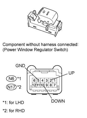
Remove the switch.
-
Measure the resistance according to the value(s) in the table below.
Standard resistance for LHD: Tester Connection Switch Condition Specified Condition N6-2 (UP) - N6-5 (GND) Manual UP operation Below 1 Ω N6-10 (DOWN) - N6-5 (GND) Manual DOWN operation Below 1 Ω for RHD: Tester Connection Switch Condition Specified Condition N17-2 (UP) - N17-5 (GND) Manual UP operation Below 1 Ω N17-10 (DOWN) - N17-5 (GND) Manual DOWN operation Below 1 Ω
NG
REPLACE FRONT POWER WINDOW REGULATOR SWITCH ASSEMBLY (for Front Passenger) Click here
OK
-
-
CHECK HARNESS AND CONNECTOR (FRONT PASSENGER SIDE DOOR ECU - FRONT PASSENGER SIDE SWITCH)
-
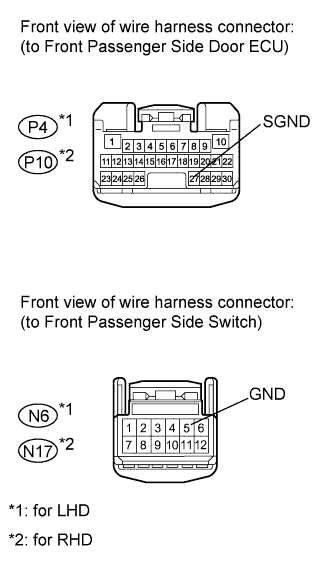
Disconnect the P4*1 or P10*2 ECU connector.
-
Disconnect the N6*1 or N17*2 switch connector.
-
Measure the resistance according to the value(s) in the table below.
Standard resistance for LHD: Tester Connection Condition Specified Condition P4-27 (SGND) - N6-5 (GND) Always Below 1 Ω P4-27 (SGND) or N6-5 (GND) - Body ground Always 10 kΩ or higher for RHD: Tester Connection Condition Specified Condition P10-27 (SGND) - N17-5 (GND) Always Below 1 Ω P10-27 (SGND) or N17-5 (GND) - Body ground Always 10 kΩ or higher
NG
REPAIR OR REPLACE HARNESS OR CONNECTOR
OK
-
-
CHECK HARNESS AND CONNECTOR (FRONT PASSENGER SIDE DOOR ECU - FRONT PASSENGER SIDE MOTOR)
-
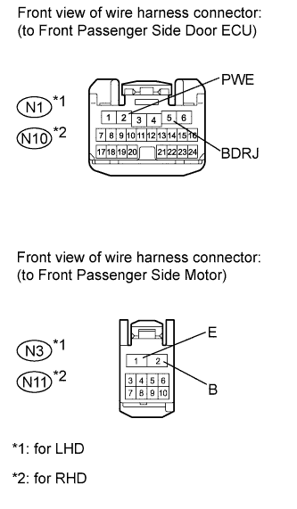
Disconnect the N1*1 or N10*2 ECU connector.
-
Disconnect the N3*1 or N11*2 motor connector.
-
Measure the resistance according to the value(s) in the table below.
Standard resistance for LHD: Tester Connection Condition Specified Condition N1-5 (BDRJ) - N3-2 (B) Always Below 1 Ω N1-2 (PWE) - N3-1 (E) Always Below 1 Ω N1-5 (BDRJ) or N3-2 (B) - Body ground Always 10 kΩ or higher N1-2 (PWE) or N3-1 (E) - Body ground Always 10 kΩ or higher for RHD: Tester Connection Condition Specified Condition N10-5 (BDRJ) - N11-2 (B) Always Below 1 Ω N10-2 (PWE) - N11-1 (E) Always Below 1 Ω N10-5 (BDRJ) or N11-2 (B) - Body ground Always 10 kΩ or higher N10-2 (PWE) or N11-1 (E) - Body ground Always 10 kΩ or higher
NG
REPAIR OR REPLACE HARNESS OR CONNECTOR
OK
-
-
CHECK HARNESS AND CONNECTOR (FRONT PASSENGER SIDE SWITCH - FRONT PASSENGER SIDE MOTOR)
-
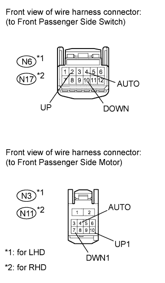
Disconnect the N6*1 or N17*2 switch connector.
-
Disconnect the N3*1 or N11*2 motor connector.
-
Measure the resistance according to the value(s) in the table below.
Standard resistance for LHD: Tester Connection Condition Specified Condition N6-2 (UP) - N3-10 (UP1) Always Below 1 Ω N6-10 (DOWN) - N3-7 (DWN1) Always Below 1 Ω N6-4 (AUTO) - N3-4 (AUTO) Always Below 1 Ω N6-2 (UP) or N3-10 (UP1) - Body ground Always 10 kΩ or higher N6-10 (DOWN) or N3-7 (DWN1) - Body ground Always 10 kΩ or higher N6-4 (AUTO) or N3-4 (AUTO) - Body ground Always 10 kΩ or higher for RHD: Tester Connection Condition Specified Condition N17-2 (UP) - N11-10 (UP1) Always Below 1 Ω N17-10 (DOWN) - N11-7 (DWN1) Always Below 1 Ω N17-4 (AUTO) - N11-4 (AUTO) Always Below 1 Ω N17-2 (UP) or N11-10 (UP1) - Body ground Always 10 kΩ or higher N17-10 (DOWN) or N11-7 (DWN1) - Body ground Always 10 kΩ or higher N17-4 (AUTO) or N11-4 (AUTO) - Body ground Always 10 kΩ or higher Result: Result Proceed to NG A OK (for LHD) B OK (for RHD) C
B
REPLACE FRONT POWER WINDOW REGULATOR MOTOR ASSEMBLY RH Click here
C
REPLACE FRONT POWER WINDOW REGULATOR MOTOR ASSEMBLY LH Click here
A
REPAIR OR REPLACE HARNESS OR CONNECTOR
-
-
READ VALUE USING INTELLIGENT TESTER (REAR MOTOR LH)
-
Connect the intelligent tester to the DLC3.
-
Turn the engine switch on (IG).
-
Turn ON the intelligent tester.
-
Enter the following menus.
-
Select: Body / RL-Door Motor / Data List /
-
-
According to the display on tester, read the "Data List".
RL-Door Motor: Tester Display Measurement Item/Range Normal Condition Diagnostic Note RL Door P/W Auto SW Rear power window LH remote auto UP/DOWN switch signal / ON or OFF ON: Rear power window LH remote auto UP/DOWN switch on master switch operated
OFF: Rear power window LH switch on master switch not operated
- RL Door P/W Up SW Rear power window LH remote manual UP switch signal / ON or OFF ON: Rear power window LH remote manual UP switch on master switch operated
OFF: Rear power window LH switch on master switch not operated
- RL Door P/W Down SW Rear power window LH remote manual DOWN switch signal / ON or OFF ON: Rear power window LH remote manual DOWN switch on master switch operated
OFF: Rear power window LH switch on master switch not operated
- OK Tester display changes normally when rear power window switch LH is operated.
NG
INSPECT REAR POWER WINDOW REGULATOR SWITCH ASSEMBLY (for Rear LH) Click here
OK
END (DUE TO KEEPING SWITCH OPERATED FOR 20 SECONDS OR MORE)
-
-
INSPECT REAR POWER WINDOW REGULATOR SWITCH ASSEMBLY (for Rear LH)
-
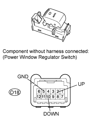
Remove the switch.
-
Measure the resistance according to the value(s) in the table below.
Standard resistance Tester Connection Switch Condition Specified Condition O18-2 (UP) - O18-5 (GND) Manual UP operation Below 1 Ω O18-10 (DOWN) - O18-5 (GND) Manual DOWN operation Below 1 Ω
NG
REPLACE REAR POWER WINDOW REGULATOR SWITCH ASSEMBLY (for Rear LH) Click here
OK
-
-
CHECK HARNESS AND CONNECTOR (REAR DOOR ECU LH - REAR SWITCH LH)
-
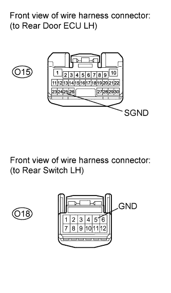
Disconnect the O15 ECU connector.
-
Disconnect the O18 switch connector.
-
Measure the resistance according to the value(s) in the table below.
Standard resistance Tester Connection Condition Specified Condition O15-25 (SGND) - O18-5 (GND) Always Below 1 Ω O15-25 (SGND) or O18-5 (GND) - Body ground Always 10 kΩ or higher
NG
REPAIR OR REPLACE HARNESS OR CONNECTOR
OK
-
-
CHECK HARNESS AND CONNECTOR (REAR DOOR ECU LH - REAR MOTOR LH)
-
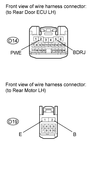
Disconnect the O14 ECU connector.
-
Disconnect the O19 motor connector.
-
Measure the resistance according to the value(s) in the table below.
Standard resistance Tester Connection Condition Specified Condition O14-5 (BDRJ) - O19-2 (B) Always Below 1 Ω O14-2 (PWE) - O19-1 (E) Always Below 1 Ω O14-5 (BDRJ) or O19-2 (B) - Body ground Always 10 kΩ or higher O14-2 (PWE) or O19-1 (E) - Body ground Always 10 kΩ or higher
NG
REPAIR OR REPLACE HARNESS OR CONNECTOR
OK
-
-
CHECK HARNESS AND CONNECTOR (REAR SWITCH LH - REAR MOTOR LH)
-
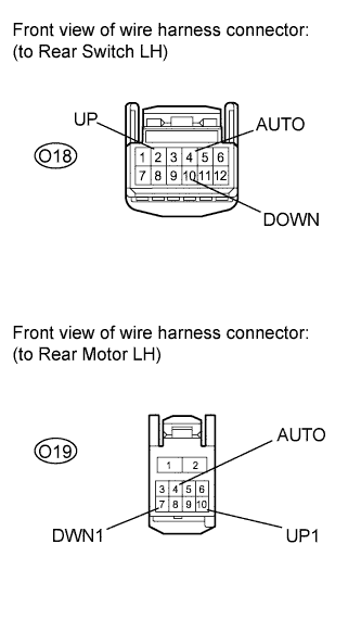
Disconnect the O18 switch connector.
-
Disconnect the O19 motor connector.
-
Measure the resistance according to the value(s) in the table below.
Standard resistance Tester Connection Condition Specified Condition O18-2 (UP) - O19-10 (UP1) Always Below 1 Ω O18-10 (DOWN) - O19-7 (DWN1) Always Below 1 Ω O18-4 (AUTO) - O19-4 (AUTO) Always Below 1 Ω O18-2 (UP) or O19-10 (UP1) - Body ground Always 10 kΩ or higher O18-10 (DOWN) or O19-7 (DWN1) - Body ground Always 10 kΩ or higher O18-4 (AUTO) or O19-4 (AUTO) - Body ground Always 10 kΩ or higher
NG
REPAIR OR REPLACE HARNESS OR CONNECTOR
OK
REPLACE REAR POWER WINDOW REGULATOR MOTOR ASSEMBLY (for Rear LH) Click here
-
-
READ VALUE USING INTELLIGENT TESTER (REAR MOTOR RH)
-
Connect the intelligent tester to the DLC3.
-
Turn the engine on (IG).
-
Turn ON the intelligent tester.
-
Enter the following menus.
-
Select: Body / RR-Door Motor / Data List /
-
-
According to the display on tester, read the "Data List".
RR-Door Motor: Tester Display Measurement Item/Range Normal Condition Diagnostic Note RR Door P/W Auto SW Rear power window RH remote auto UP/DOWN switch signal / ON or OFF ON: Rear power window RH remote auto UP/DOWN switch on master switch operated
OFF: Rear power window RH switch on master switch not operated
- RR Door P/W Up SW Rear power window RH remote manual UP switch signal / ON or OFF ON: Rear power window RH remote manual UP switch on master switch operated
OFF: Rear power window RH switch on master switch not operated
- RR Door P/W Down SW Rear power window RH remote manual DOWN switch signal / ON or OFF ON: Rear power window RH remote manual DOWN switch on master switch operated
OFF: Rear power window RH switch on master switch not operated
- OK Tester display changes normally when rear power window switch RH is operated.
NG
INSPECT REAR POWER WINDOW REGULATOR SWITCH ASSEMBLY (for Rear RH) Click here
OK
END (DUE TO KEEPING SWITCH OPERATED FOR 20 SECONDS OR MORE)
-
-
INSPECT REAR POWER WINDOW REGULATOR SWITCH ASSEMBLY (for Rear RH)
-
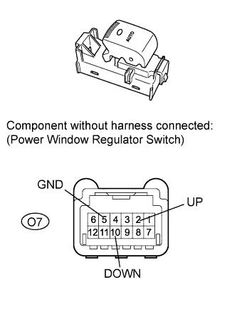
Remove the switch.
-
Measure the resistance according to the value(s) in the table below.
Standard resistance Tester Connection Switch Condition Specified Condition O7-2 (UP) - O7-5 (GND) Manual UP operation Below 1 Ω O7-10 (DOWN) - O7-5 (GND) Manual DOWN operation Below 1 Ω
NG
REPLACE REAR POWER WINDOW REGULATOR SWITCH ASSEMBLY (for Rear RH) Click here
OK
-
-
CHECK HARNESS AND CONNECTOR (REAR DOOR ECU RH - REAR SWITCH RH)
-
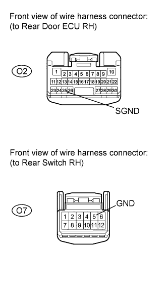
Disconnect the O2 ECU connector.
-
Disconnect the O7 switch connector.
-
Measure the resistance according to the value(s) in the table below.
Standard resistance Tester Connection Condition Specified Condition O2-25 (SGND) - O7-5 (GND) Always Below 1 Ω O2-25 (SGND) or O7-5 (GND) - Body ground Always 10 kΩ or higher
NG
REPAIR OR REPLACE HARNESS OR CONNECTOR
OK
-
-
CHECK HARNESS AND CONNECTOR (REAR DOOR ECU RH - REAR MOTOR RH)
-
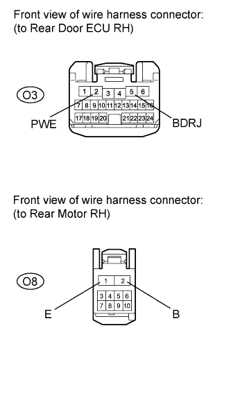
Disconnect the O3 ECU connector.
-
Disconnect the O8 motor connector.
-
Measure the resistance according to the value(s) in the table below.
Standard resistance Tester Connection Condition Specified Condition O3-5 (BDRJ) - O8-2 (B) Always Below 1 Ω O3-2 (PWE) - O8-1 (E) Always Below 1 Ω O3-5 (BDRJ) or O8-2 (B) - Body ground Always 10 kΩ or higher O3-2 (PWE) or O8-1 (E) - Body ground Always 10 kΩ or higher
NG
REPAIR OR REPLACE HARNESS OR CONNECTOR
OK
-
-
CHECK HARNESS AND CONNECTOR (REAR SWITCH RH - REAR MOTOR RH)
-
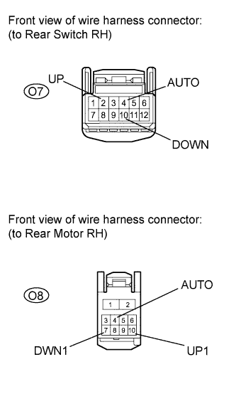
Disconnect the O7 switch connector.
-
Disconnect the O8 motor connector.
-
Measure the resistance according to the value(s) in the table below.
Standard resistance Tester Connection Condition Specified Condition O7-2 (UP) - O8-10 (UP1) Always Below 1 Ω O7-10 (DOWN) - O8-7 (DWN1) Always Below 1 Ω O7-4 (AUTO) - O8-4 (AUTO) Always Below 1 Ω O7-2 (UP) or O8-10 (UP1) - Body ground Always 10 kΩ or higher O7-10 (DOWN) or O8-7 (DWN1) - Body ground Always 10 kΩ or higher O7-4 (AUTO) or O8-4 (AUTO) - Body ground Always 10 kΩ or higher
NG
REPAIR OR REPLACE HARNESS OR CONNECTOR
OK
REPLACE REAR POWER WINDOW REGULATOR MOTOR ASSEMBLY (for Rear RH) Click here
-