HORN SYSTEM Vehicle Horn does not Sound
DESCRIPTION
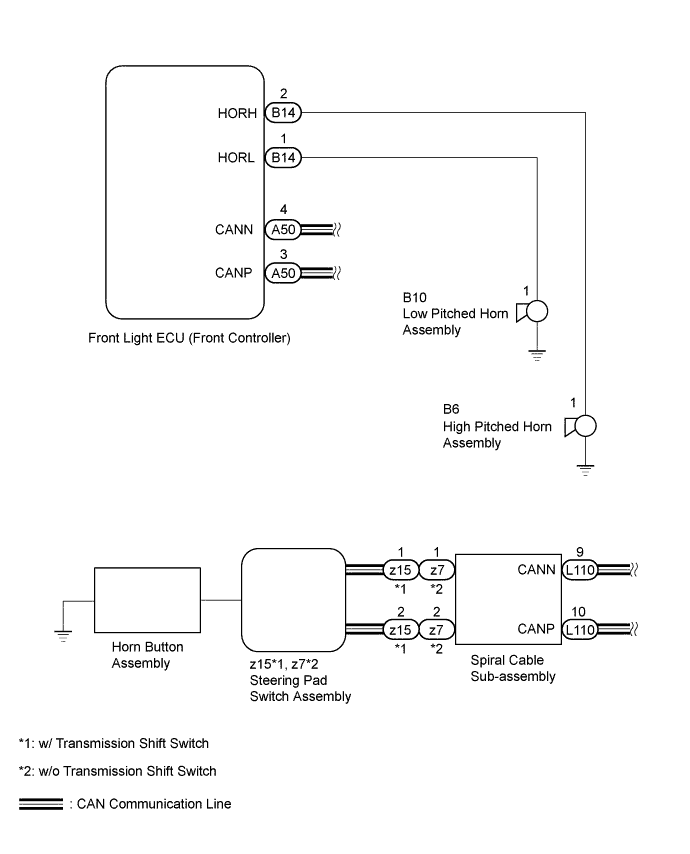
When the horn button assembly is pressed, a signal is sent from the horn button assembly through the steering pad switch assembly to the spiral cable sub-assembly. The spiral cable sub-assembly and front light ECU (front controller) communicate via the CAN line. The front light ECU (front controller) receives the signal and sends it to the vehicle horns, causing the horns to sound.
WIRING DIAGRAM
INSPECTION PROCEDURE
PROCEDURE
-
READ VALUE USING INTELLIGENT TESTER (HORN SWITCH)
-
Using the intelligent tester, read the Data List Click here.
-
Intelligent tester
Steering Pad Switch Tester Display Measurement Item/Range Normal Condition Diagnostic Note Horn switch Horn button status
/ ON or OFF
OK: Horn button is pressed
OFF: Horn button is not pressed
- OK ON (horn button is pressed) appears on screen.
-
NG 
CHECK HORN BUTTON ASSEMBLY Click here
OK 
-
-
INSPECT HORN ASSEMBLY
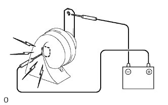
-
Remove the horn for low pitched horn Click here or high pitched horn Click here.
-
Check operation of the horn.
OK Measurement Condition Specified Condition Battery positive (+) → Terminal 1
Battery negative (-) → Horn bracket
Horn sounds Result Result Proceed to OK A NG (for High Pitched Horn) B NG (for Low Pitched Horn) C
B 
REPLACE HIGH PITCHED HORN ASSEMBLY Click here
C
REPLACE LOW PITCHED HORN ASSEMBLY Click here
A
-
-
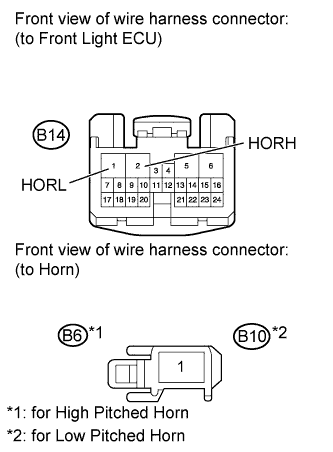
CHECK HARNESS AND CONNECTOR (FRONT LIGHT ECU - HORN)
-
Disconnect the B14 ECU connector.
-
Disconnect the B6*1 or B10*2 horn connector.
-
*1: for High pitched horn
-
*2: for Low pitched horn
-
-
Measure the resistance according to the value(s) in the table below.
Standard resistance for High pitched horn Tester Connection Condition Specified Condition B14-2 (HORH) - B6-1 Always Below 1 Ω B14-2 (HORH) or B6-1 - Body ground Always 10 kΩ or higher for Low pitched horn Tester Connection Condition Specified Condition B14-1 (HORL) - B10-1 Always Below 1 Ω B14-1 (HORL) or B10-1 - Body ground Always 10 kΩ or higher
NG
REPAIR OR REPLACE HARNESS OR CONNECTOR
OK
-
-
CHECK STEERING PAD SWITCH ASSEMBLY
-
Temporarily replace the steering pad switch assembly with a new or normally functioning one Click here.
-
Check that the vehicle horns operate normally.
OK Vehicle horns operate normally.
NG
REPLACE FRONT LIGHT ECU (FRONT CONTROLLER)
OK 
END (STEERING PAD SWITCH ASSEMBLY WAS DEFECTIVE)
-
-
CHECK HORN BUTTON ASSEMBLY
-
Temporarily replace the horn button assembly with a new or normally functioning one Click here.
-
Check that the vehicle horns operate normally.
OK Vehicle horns operate normally.
NG
CHECK STEERING PAD SWITCH ASSEMBLY Click here
OK
END (HORN BUTTON ASSEMBLY WAS DEFECTIVE)
-
-
CHECK STEERING PAD SWITCH ASSEMBLY
-
Temporarily replace the steering pad switch assembly with a new or normally functioning one Click here.
-
Check that the vehicle horns operate normally.
OK Vehicle horns operate normally.
NG
REPLACE FRONT LIGHT ECU (FRONT CONTROLLER)
OK
END (STEERING PAD SWITCH ASSEMBLY WAS DEFECTIVE)
-