HORN SYSTEM TERMINALS OF ECU

-
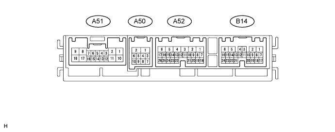
CHECK FRONT LIGHT ECU (FRONT CONTROLLER)
-
Disconnect the A50 and A52 ECU connectors.
-
Measure the resistance and voltage according to the value(s) in the table below.
Terminal No. (Symbols) Wiring Color Terminal Description Condition Specified Condition A52-5 (ALTB) - Body ground L - Body ground +B power supply Always 11 to 14 V A52-1 (BATB) - Body ground P - Body ground +B power supply Always 11 to 14 V A50-1 (FMB3) - Body ground LG - Body ground +B power supply Always 11 to 14 V A50-5 (FMIG) - Body ground Y - Body ground IG power supply Engine switch on (IG) 11 to 14 V A50-2 (E) - Body ground W-B - Body ground Ground Always Below 1 Ω -
Reconnect the A50 and A52 ECU connectors.
-
Measure the voltage according to the value(s) in the table below.
Terminal No. (Symbols) Wiring Color Terminal Description Condition Specified Condition B14-1 (HORL) - Body ground B - Body ground Horn (low pitched) signal Horn is sounding 11 to 14 V B14-2 (HORH) - Body ground B - Body ground Horn (high pitched) signal Horn is sounding 11 to 14 V
-
-
CHECK STEERING PAD SWITCH ASSEMBLY
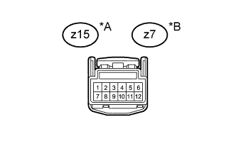
Text in Illustration *A w/ Transmission Shift Switch *B w/o Transmission Shift Switch
-
Measure the voltage according to the value(s) in the table below.
Terminal No. (Symbols) Wiring Color Terminal Description Condition Specified Condition z15-12 - Body ground*1 W - Body ground +B power supply Always 11 to 14 V z7-12 - Body ground*2 R - Body ground +B power supply Always 11 to 14 V
-
*1: w/ Transmission Shift Switch
-
*2: w/o Transmission Shift Switch
-
-