BATTERY CURRENT SENSOR INSTALLATION

-
INSTALL GROUND WIRE (BATTERY CURRENT SENSOR)
-
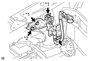
Text in Illustration *1 Bolt A *2 Bolt B for LHD:
-
Install the ground wire (battery current sensor) with the 2 bolts A.
- Torque:
- 11.5 N*m { 117 kgf*cm, 8 ft.*lbf }
-
Install the bolt B to connect the ground wire harness to the ground wire (battery current sensor).
- Torque:
- 10 N*m { 102 kgf*cm, 7 ft.*lbf }
-
Connect the connector.
-
-
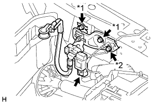
Text in Illustration *1 Bolt A *2 Bolt B for RHD:
-
Install the ground wire (battery current sensor) with the 2 bolts A.
- Torque:
- 11.5 N*m { 117 kgf*cm, 8 ft.*lbf }
-
Install the bolt B to connect the ground wire harness to the ground wire (battery current sensor).
- Torque:
- 10 N*m { 102 kgf*cm, 7 ft.*lbf }
-
Connect the connector.
-
-
-
INSTALL FRONT FENDER UPPER PROTECTOR RH (for LHD)
Tech Tips
Use the same procedure described for the LH side.
-
REMOVE FRONT FENDER UPPER PROTECTOR LH (for RHD)
-
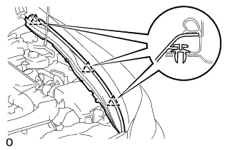
Attach the clips to install the fender protector upper LH.
-
-
INSTALL ENGINE ROOM SIDE COVER RH (for LHD)
-
Install the engine room side cover RH with the 5 clips.
-
-
REMOVE ENGINE ROOM SIDE COVER LH (for RHD)
-
Install the engine room side cover LH with the 5 clips.
-
-
CONNECT CABLE TO NEGATIVE BATTERY TERMINAL
Note
When disconnecting the cable, some systems need to be initialized after the cable is reconnected Click here.
-
INSTALL COWL TOP VENTILATOR LOUVER
-

Install the 6 clips and cowl top ventilator louver RH.
Note
Be sure to install the cowl top ventilator louver RH properly. If it is not installed properly, water may enter the engine room and cause malfunctions.
-