BATTERY CURRENT SENSOR INSPECTION

Tech Tips
-
Use the same procedure for RHD and LHD vehicles.
-
The procedure listed below is for LHD vehicles.
-
INSPECT GROUND WIRE (BATTERY CURRENT SENSOR)
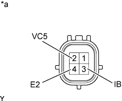
Text in Illustration *a Component without harness connected
{Ground Wire (Battery Current Sensor)}
-
Measure the resistance according to the value(s) in the table below.
Standard Resistance Tester Connection Specified Condition Tester (+) → 2 (VC5)
Tester (-) → 4 (E2)
3 k to 10 kΩ Tester (+) → 2 (VC5)
Tester (-) → 3 (IB)
0.5 kΩ or less Tester (+) → 3 (IB)
Tester (-) → 4 (E2)
3 k to 10 kΩ If the result is not as specified, replace the ground wire (battery current sensor).
-
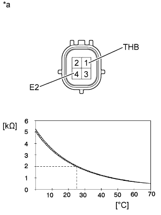
Text in Illustration *a Component without harness connected
{Ground Wire (Battery Current Sensor)}
Measure the resistance according to the value(s) in the table below.
Standard Resistance Tester Connection Condition Specified Condition 1 (THB) - 4 (E2) 20 to 30°C (68 to 86°F) 1.5 k to 2.5 kΩ (0 to 70°C (32 to 158°F)) (0.3 k to 6.0 kΩ) Note
The temperature shown in the condition is for the area surrounding the sensor, not the sensor itself.
If the result is not as specified, replace the ground wire (battery current sensor).
-