NIGHT VIEW CAMERA INSTALLATION

Tech Tips
-
Use the same procedure for RHD and LHD vehicles.
-
The procedure listed below is for LHD vehicles.
-
INSTALL OBJECT RECOGNITION WITH NIGHT VIEW CAMERA
Note
-
Do not touch the camera lens when removing or installing the camera.
-
Do not use a camera which has been dropped or subjected to an impact.
-
If the camera is not installed securely, the system may not operate properly. Therefore, be sure to install the camera securely.
-
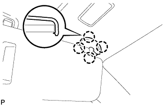
Push the bracket to attach the clip.
-
Allow the wire harness to hang down.
-
Do not press the sensor, as it may become deformed.
-
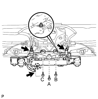
Temporarily install the object recognition with night view camera with the clip.
-
Install the 3 bolts in alphabetical order.
- Torque:
- 9.0 N*m { 92 kgf*cm, 80 in.*lbf }
-
Attach the claw to connect the connector clamp.
-
Attach the 2 wire harness clamps.
-
Connect the 3 connectors.
-
Return the roof headlining to its original position.
-
-
INSTALL INNER REAR VIEW MIRROR ASSEMBLY
-
w/o Automatic High Beam System, Adaptive High Beam System:
-
w/ Automatic High Beam System, Adaptive High Beam System:
-
-
INSTALL RAIN SENSOR COVER
Note
When removing and installing the rain sensor cover, do not apply force to the object recognition camera areas labeled "X".
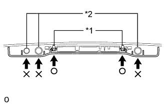
Text in Illustration *1 Clip *2 Camera
-
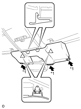
While being careful not to apply force to the camera area, attach the 2 claws and 2 clips to install the rain sensor cover.
-
Push the stopper as shown in the illustration to fix the cover in place.
Text in Illustration *1 Stopper
-
-
INSTALL VISOR HOLDER
Tech Tips
Use the same procedure to install the visor holder on the other side.
-
Attach the 2 claws to install the visor holder.
-
Push in the visor holder and turn it approximately 45° as shown in the illustration.
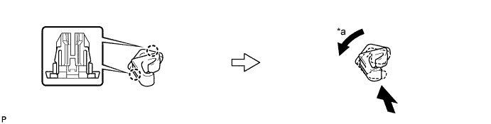
Text in Illustration *a 45° - -
-
-
INSTALL VISOR ASSEMBLY LH
-
Install the visor assembly with the 2 screws.
-
-
INSTALL VISOR ASSEMBLY RH
Tech Tips
Use the same procedure described for the LH side.
-
INSTALL VISOR BRACKET COVER
Tech Tips
Use the same procedure to install the cover on the other side.
-
Attach the 4 claws to install the visor bracket cover.
-
-
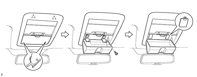
INSTALL MAP LIGHT ASSEMBLY
-
Connect the 2 connectors.
-
Attach the 2 clips to install the map light assembly.
-
Install the 2 screws.
-
Attach the 2 claws to close the 2 covers.
-
-
ADJUST OBJECT RECOGNITION CAMERA
Note
-
Make sure there are no black and white patterned objects in front of the vehicle.
-
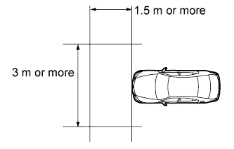
Perform the measurement in a place with no wind, and make sure there is a distance of 1.5 m (4.92 ft.) or more in front of the vehicle and that the surface is level with no obstacles.
-
Check that there are no reflective materials in the surroundings or on the ground within a 3 m (9.84 ft.) or more x 3 m (9.84 ft.) or more area in front of the vehicle.
-
Perform the inspection in a bright area.
-
Turn the taillights on.
-
Do not turn the headlights on.
-
Beam axis learning preparation
-
Move the vehicle to a level surface.
-
Make sure the engine oil in the vehicle is at the specified amount.
-
Make sure the engine coolant in the vehicle is at the specified amount.
-
Make sure the fuel tank is full.
-
Make sure the spare tire is in the vehicle. (w/ Spare Tire)
-
Make sure the standard tools are in the vehicle.
-
Make sure nobody is in the vehicle.
-
Make sure no extra loads are in the vehicle.
-
Adjust the tire pressures to the specified pressure.
-
Set the height control switch to normal.
-
Clean the front glass.
-
If the lens of the object recognition camera sensor is dirty, apply a small amount of lens cleaner to a clean, soft cloth and clean the lens.
-
-
Perform height control sensor adjustment
-
Perform the height control sensor adjustment Click here.
Note
Perform this procedure as accurately as possible.
-
-
Perform the front wheel alignment adjustment
-
Perform the front wheel alignment adjustment Click here.
Note
Perform this procedure as accurately as possible.
-
-
Perform the rear wheel alignment adjustment
-
Perform the rear wheel alignment adjustment Click here.
Note
-
Perform this procedure as accurately as possible.
-
Press the height control switch, change the vehicle height to HIGH and return it to NORM. Then repeat.
-
-
-
Target sheet creation
-
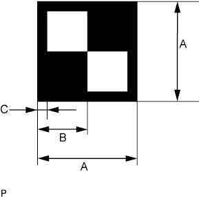
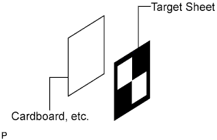
Print or copy the illustration below. Check that the dimensions are +/-5 mm of the ones in the table below.
Dimension Area Specification A 160 mm (6.30 in.) B 80 mm (3.15 in.) C 16 mm (0.630 in.) Note
-
Make sure that the black areas of the target sheets are not glossy.
-
Make sure that the borders of the black and white areas on the target sheets are straight, and are not warped or blurry.
If the print or copy's dimensions are not as specified, adjust settings and reprint or recopy the illustration so that the print or copy's dimensions are as specified.

-
-
-
Target sheet attachment
-
Place the prepared target sheet on a piece of cardboard of the same size with the black area on the top right as shown in the illustration. Then use double-sided tape to fix the target sheet in place.
Note
Do not attach reflective tape such as scotch tape, etc. to the target face as this may affect target recognition.
-
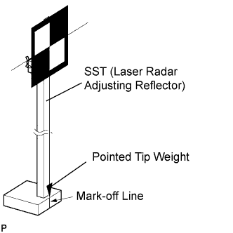
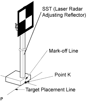
Hang a weight with a pointed tip from the center of the target sheet. Then with double-sided tape, attach the target sheet to the reflector so that the weight aligns with the mark-off line of the SST (laser radar adjusting reflector).
- SST
- 09870-60000 ( 09870-60010, 09870-60020 )
Note
-
Perform this procedure as accurately as possible.
-
Attach the target sheet so that it is horizontal with the ground.
-
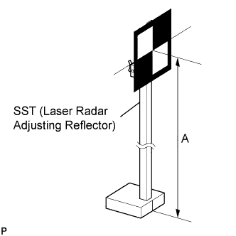
Move the reflector up and down to position the center of the target at the height shown in the illustration, and then fix it in place.
Dimension A 1270 mm (4.17 ft.) - SST
- 09870-60000 ( 09870-60010, 09870-60020 )
Note
Perform this procedure as accurately as possible.
-
-
Target placement point measurement
Note
-
Perform this procedure as accurately as possible.
-
Do not place reflective materials in the area behind the target.
-
Make sure there are no patterns on the wall behind the target.
-
Make sure the distance between the target and wall is within 3 m (9.84 ft.).
-
Do not place black and white patterned objects near the target.
-
Make sure the target's shadow is not on the wall, as the camera may have a recognition error.
-
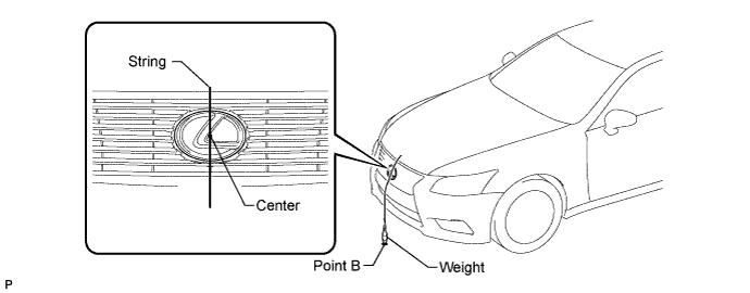
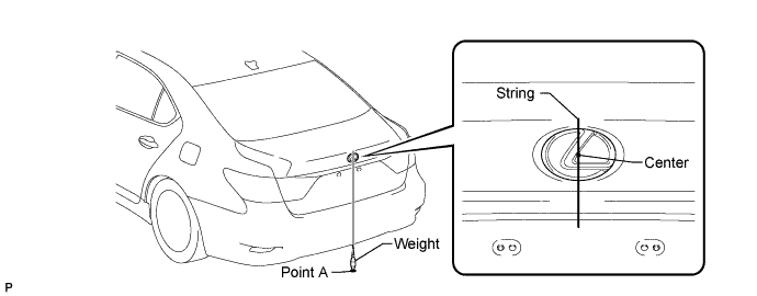
From the center of the front bumper (center of the emblem), hang a weight with a pointed tip, and mark point B on the ground.
-
From the center of the rear bumper (center of the emblem), hang a weight with a pointed tip, and mark point A on the ground.
-
Using a piece of string that uses point A as a starting point and that passes through point B, make a straight line on the ground ahead of the vehicle 2 m (6.56 ft.) or more from point B.
Tech Tips
-
Make sure to secure the string (using tape, etc.) when it is taut.
-
Lightly flick the string with your fingers several times to confirm that the string is aligned above point B.
-
-
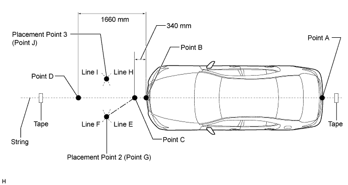
Mark point C at a position 340 mm (1.12 ft.) from point B.
-
Mark point D at a position 1660 mm (5.44 ft.) from point B.
-
Using the string, mark line E at a position 1000 mm (3.28 ft.) from point C.
-
Using the string, mark line H at a position 1000 mm (3.28 ft.) from point C.
-
Using the string, mark line F at a position 1000 mm (3.28 ft.) from point D.
-
Using the string, mark line I at a position 1000 mm (3.28 ft.) from point D.
-
Mark point G at the point where line E and line F intersect (placement point 2).
-
Mark point J at the point where line H and line I intersect (placement point 3).
-
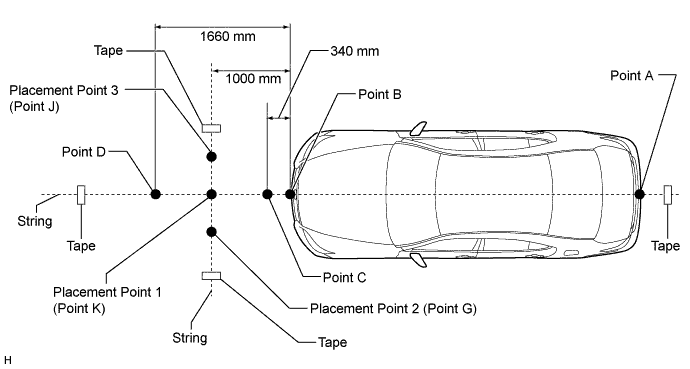
Secure a string that connects point G and point J to the ground (target placement line).
-
Mark point K at the intersection between the string connecting points C and D and the string connecting points G and J (placement point 1).
-
Confirm the distance measurements for points K, G, and J (placement points 1, 2, and 3) again.
-
-
Object recognition camera sensor height measurement
Note
-
Do not place black and white patterned objects near the target.
-
Face the vehicle toward a wall with no patterns, or make sure the background behind the target has no patterns.
-
Perform this procedure as accurately as possible.
-
Do not place reflective materials in the area behind the target.
-
Make sure there are no patterns on the wall behind the target.
-
Make sure the distance between the target and wall is within 3 m (9.84 ft.).
-
Make sure the target's shadow is not on the wall as the camera may have a recognition error.
-
Measure the distance (X mm or in.) from the ground to point H for the front left wheel arch.
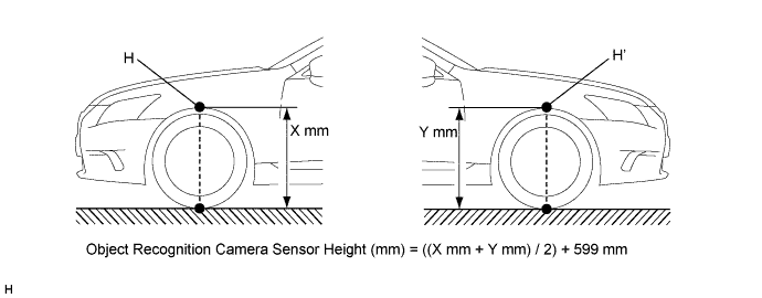
-
Measure the distance (Y mm or in.) from the ground to point H' for the front right wheel arch.
-
The average of the 2 distances (X mm or in., Y mm or in.) plus 599 mm (1.96 ft.) is the height of the object recognition camera sensor.
-
-
Memorize camera/target position
Note
-
Close all doors.
-
Perform the procedure with no one in the vehicle.
-
During the procedure, do not lean on the vehicle.
-
Illuminate the clearance lights.
-
Do not illuminate the headlights.
-
When using the intelligent tester:
-
Connect the intelligent tester to the DLC3.
-
Turn the engine switch on (IG).*1
-
Turn the intelligent tester main switch ON and turn the LKA main switch ON.
-
Select "LKA System" from the display screen.
-
Select "Utility" from the display screen.
-
Select "Camera/target position memory" from the display screen.
-
Follow the tester display and select "Next".
-
-
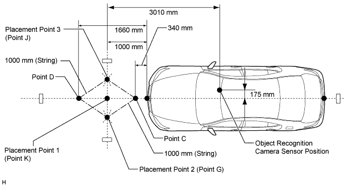
Input the measured height of the object recognition camera sensor and the horizontal position of the camera "175 mm (6.89 in.)" into the input screen. Then press the "Next" button on the display screen.
-
Input "3010 mm (119 in.)" for the distance from the camera to the target and "1270 mm (50.0 in.)" for the height of the target into the input screen. Then press the "Next" button on the display screen.
-
Press the "Exit" button to finish the camera/target position memory mode.
Note
If "Error Camera/target position memory" is displayed on the screen, press the "Try Again" button, and repeat from procedure *1 again.
-
-
Beam axis learning
-
Select "LKA System" from the display screen.*1
-
Select "Utility" from the display screen.
-
Select "Camera axis adjust" from the display screen.
-
Follow the tester display and select "Next".
-
Align the target sheet with the target placement line and align the mark-off line with placement point 1 (point K).
-
Check that the screen displays beam axis learning for target 1, and then press the "Next" button on the display screen.
-

Align the target sheet with the target placement line and align the mark-off line with placement point 2 (point G).
-
Check that the screen displays beam axis learning for target 2, and then press the "Next" button on the display screen.
Note
Within 3 minutes after the screen displays the beam axis learning for target 2, move the target and press the "Next" button on the display screen.
-

Align the target sheet with the target placement line and align the mark-off line with placement point 3 (point J).
-
Check that the screen displays beam axis learning for target 3, and then press the "Next" button on the display screen.
Note
Within 3 minutes after the screen displays the beam axis learning for target 3, move the target and press the "Next" button on the display screen.
-
Press the "Exit" button to finish the beam axis learning mode.
Note
-
Height of the target.
-
Distance from the object recognition camera sensor to the target.
-
Orientation of the target (black area positioned on the top right).
-
If surrounding area is bright enough.
-
If black and white patterned objects are placed near the target.
If "Error camera axis adjust" is displayed on the screen, press the "Exit" button. Then after checking the conditions below, turn the engine switch on (IG) and off and repeat from procedure *1 again.
-
-
-
-
ADJUST NIGHT VIEW CAMERA