NIGHT VIEW SYSTEM Night View Image is not Normal
DESCRIPTION
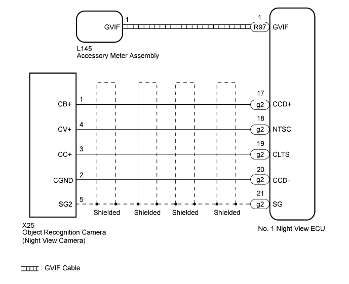
The No. 1 night view ECU receives the front image signal from the object recognition camera (night view camera). Using the digital (GVIF cable) signal line, the image data is sent to the accessory meter assembly.
WIRING DIAGRAM
INSPECTION PROCEDURE
Note
When the No. 1 night view ECU and/or object recognition camera (night view camera) is replaced, perform object recognition camera (night view camera) adjustment Click here.
PROCEDURE
-
CHECK FOR DIRT AND DAMAGE
-
Check that the area of the front windshield glass in front of the object recognition camera (night view camera), object recognition camera (night view camera) lens and/or headlights lens is free of dirt and damage.
OK There is no dirt or damage.
NG 
CLEAN OR REPLACE DAMAGED PARTS
OK 
-
-
CHECK HARNESS AND CONNECTOR (NO. 1 NIGHT VIEW ECU - OBJECT RECOGNITION CAMERA [NIGHT VIEW CAMERA])
-
Disconnect the g2 No. 1 night view ECU connector.
-
Disconnect the X25 object recognition camera (night view camera) connector.
-
Measure the resistance according to the value(s) in the table below.
Standard Resistance Tester Connection Condition Specified Condition g2-17 (CCD+) - X25-1 (CB+) Always Below 1 Ω g2-18 (NTSC) - X25-4 (CV+) Always Below 1 Ω g2-19 (CLTS) - X25-3 (CC+) Always Below 1 Ω g2-20 (CCD-) - X25-2 (CGND) Always Below 1 Ω g2-21 (SG) - X25-5 (SG2) Always Below 1 Ω g2-17 (CCD+) - Body ground Always 10 kΩ or higher g2-18 (NTSC) - Body ground Always 10 kΩ or higher g2-19 (CLTS) - Body ground Always 10 kΩ or higher g2-20 (CCD-) - Body ground Always 10 kΩ or higher g2-21 (SG) - Body ground Always 10 kΩ or higher g2-17 (CCD+) - g2-18 (NTSC) Always 10 kΩ or higher g2-17 (CCD+) - g2-19 (CLTS) Always 10 kΩ or higher g2-17 (CCD+) - g2-20 (CCD-) Always 10 kΩ or higher g2-17 (CCD+) - g2-21 (SG) Always 10 kΩ or higher g2-18 (NTSC) - g2-19 (CLTS) Always 10 kΩ or higher g2-18 (NTSC) - g2-20 (CCD-) Always 10 kΩ or higher g2-18 (NTSC) - g2-21 (SG) Always 10 kΩ or higher g2-19 (CLTS) - g2-20 (CCD-) Always 10 kΩ or higher g2-19 (CLTS) - g2-21 (SG) Always 10 kΩ or higher g2-20 (CCD-) - g2-21 (SG) Always 10 kΩ or higher
NG
REPAIR OR REPLACE HARNESS OR CONNECTOR
OK
-
-
CHECK OBJECT RECOGNITION CAMERA (NIGHT VIEW CAMERA)
-
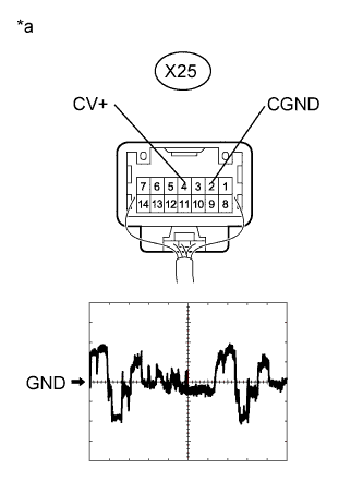
Text in Illustration *a Component with harness connected
(Object Recognition Camera [Night View Camera])
Measure the pulse from the rear of the object recognition camera (night view camera).
Measurement Condition Item Content Terminal No. (Symbol) X25-4 (CV+) - X25-2 (CGND) Tool Setting 200 mV/DIV., 10 μs./DIV. Condition Night view system operating and image output to accessory meter assembly OK The pulse changes according to the image from object recognition camera (night view camera).
NG
REPLACE OBJECT RECOGNITION CAMERA (NIGHT VIEW CAMERA) Click here
OK
-
-
REPLACE HARNESS AND CONNECTOR (GVIF CABLE)
-
Temporarily replace the wire harness and connector (GVIF cable) with a new or normally functioning one.
NEXT
-
-
CHECK SYMPTOMS
-
Confirm that the "night view image is not normal" problem symptom is not present.
OK Symptom is not present.
NG 
REPLACE NO. 1 NIGHT VIEW ECU Click here
OK 
END (GVIF CABLE IS DEFECTIVE)
-
-
REPLACE NO. 1 NIGHT VIEW ECU
-
Temporarily replace the No. 1 night view ECU with a new or normally functioning one Click here.
NEXT
-
-
ADJUST OBJECT RECOGNITION CAMERA (NIGHT VIEW CAMERA)
-
Perform object recognition camera (night view camera) adjustment Click here.
NEXT
-
-
CHECK SYMPTOMS
-
Confirm that the "night view image is not normal" problem symptom is not present.
OK Symptom is not present.
NG
REPLACE ACCESSORY METER ASSEMBLY Click here
OK
END (NO. 1 NIGHT VIEW ECU IS DEFECTIVE)
-