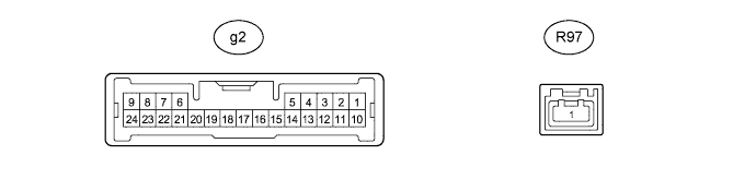
NIGHT VIEW SYSTEM TERMINALS OF ECU

-
CHECK NO. 1 NIGHT VIEW ECU
-
Disconnect the g2 No. 1 night view ECU connector.
-
Measure the resistance and voltage according to the value(s) in the table below.
Terminal No. (Symbol) Wiring Color Terminal Description Condition Specified Condition g2-6 (RE) - Body ground W-B - Body ground Ground Always Below 1 Ω g2-10 (IG) - Body ground V - Body ground IG power supply Engine switch off Below 1 V Engine switch on (IG) 11 to 14 V If the result is not as specified, there may be a malfunction on the wire harness side.
-
Reconnect the g2 No. 1 night view ECU connector.
-
Measure the voltage according to the value(s) in the table below.
Terminal No. (Symbol) Wiring Color Terminal Description Condition Specified Condition g2-13 (NVSW) - g2-6 (RE) Y - W-B Trip switch (night view switch) signal Engine switch on (IG), trip switch (night view switch) on Below 1 V Engine switch on (IG), trip switch (night view switch) off 4.8 to 5.2 V g2-17 (CCD+) - g2-20 (CCD-) R - G Night view camera power supply Night view system operating (forcibly operated using Active Test) 5.7 to 6.5 V g2-18 (NTSC) - g2-6 (RE) W - W-B Night view camera NTSC signal Night view system operating and image output to accessory meter assembly Pulse generation
(See waveform 1)
g2-19 (CLTS) - g2-6 (RE) B - W-B Night view camera control signal GTS in use (camera adjustment mode) Pulse generation g2-21 (SG) - g2-6 (RE) Shielded - W-B Night view camera shield ground Always Below 1 V
-
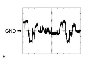
Waveform 1
Item Content Terminal No. (Symbol) g2-18 (NTSC) - g2-6 (RE) Tool Setting 200 mV/DIV., 10 μs./DIV. Condition Night view system operating and image output to accessory meter assembly
-
-
-
OBJECT RECOGNITION ECU Click here
-
DRIVING SUPPORT ECU ASSEMBLY Click here