PARKING ASSIST MONITOR SYSTEM TERMINALS OF ECU

-
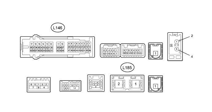
CHECK MULTI-MEDIA MODULE RECEIVER ASSEMBLY
-
Disconnect the L146 multi-media module receiver assembly connector.
-
Measure the voltage and resistance to the value(s) in the table below.
Terminal No. (Symbol) Wiring Color Terminal Description Condition Specified Condition L146-12 (GND1) - Body ground W-B - Body ground Ground Always Below 1 Ω L146-15 (IG) - L146-12 (GND1) V - W-B Power source (IG) Engine switch on (IG) 11 to 14 V Engine switch off Below 1 V L146-16 (ACC1) - L146-12 (GND1) LG - W-B Power source (ACC) Engine switch on (ACC) 11 to 14 V Engine switch off Below 1 V L146-17 (+B1) - L146-12 (GND1) R - W-B Battery Always 11 to 14 V -
Reconnect the L146 multi-media module receiver assembly connector.
-
Measure the voltage and check for pulses according to the value(s) in the table below.
Terminal No. (Symbol) Wiring Color Terminal Description Condition Specified Condition L146-1 (CANH) R CAN communication line - - L146-2 (CANL) G CAN communication line - - L146-39 (CA+) - Body ground B - Body ground Power source Engine switch on (ACC) 5.5 to 7.05 V L146-18 (V+) - L146-19 (V-) W - R Display signal Engine starts, shift lever in R, camera lens is not covered, displaying an image Pulse generation (See waveform 1) Engine starts, shift lever in R, camera lens is covered, blacking out the screen Pulse generation (See waveform 2) L146-40 (CGND) - Body ground Shielded - Body ground Shielding Always Below 1 V L146-56 (SPD) - L146-12 (GND1) V - W-B Speed signal See "Vehicle Signal Check Mode" in Operation Check Click here
- L146-57 (REV) - L146-12 (GND1) R - W-B Reverse signal See "Vehicle Signal Check Mode" in Operation Check Click here
- L185-1 (GVIF) B Video signal (Digital) - - -
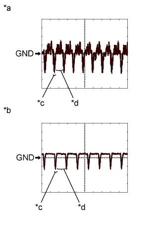
Text in Illustration *a Waveform 1 *b Waveform 2 *c Synchronization Signal *d Video Waveform Using an oscilloscope, check waveform.
Tech Tips
A waterproof connector is used for the television camera assembly. Therefore, inspect the waveform at the multi-media module receiver assembly with the connector connected.
Item Content Terminal No. (Symbol) L146-18 (V+) - L146-19 (V-) Tool Setting 200 mV/DIV., 50 μsec./ DIV. Condition Waveform 1: Engine starts, shift lever in R, camera lens is not covered, displaying an image
Waveform 2: Engine starts, shift lever in R, camera lens is covered, blacking out the screen
Tech Tips
The video waveform changes according to the image sent by the television camera assembly.
-