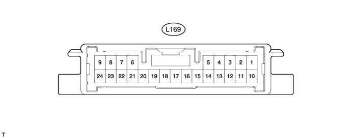
LEXUS PARKING ASSIST-SENSOR SYSTEM TERMINALS OF ECU

-
CHECK CLEARANCE WARNING ECU
-
Disconnect the L169 ECU connector.
-
Measure the voltage and resistance according to the value(s) in the table below.
Terminal No. (Symbols) Wiring Color Terminal Description Condition Specified Condition L169-15 (IG) - L169-17 (E) V - W-B IG signal / IG power source signal Engine switch off Below 1 V Engine switch on (IG) 11 to 14 V L169-17 (E) - Body ground W-B - Body ground ECU ground Always Below 1 Ω -
Reconnect the L169 ECU connector.
-
Measure the resistance, voltage and waveform according to the value(s) in the table below.
Terminal No. (Symbols) Wiring Color Terminal Description Condition Specified Condition L169-1 (CBZ) - L169-17 (E) W - W-B Front clearance warning buzzer signal Buzzer not sounding Below 1 V Buzzer sounding Waveform 2 L169-2 (EE) - L169-17 (E) B - W-B Front clearance warning buzzer signal Buzzer not sounding Below 1 V Buzzer sounding Waveform 2 L169-7 (BOR) - L169-18 (E2) B - R Rear sensor circuit power source Engine switch off Below 1 V Engine switch on (IG), clearance sonar main switch ON 7.2 to 8.8 V L169-9 (SOF) - L169-19 (E1) G - R Front sensor circuit power source Engine switch on (IG), clearance sonar main switch ON Waveform 1 L169-10 (BBZ) - L169-17 (E) W - W-B Rear clearance warning buzzer signal Engine switch off Below 1 V Engine switch on (IG) 11 to 14 V L169-11 (EF) - L169-17 (E) B - W-B Rear clearance warning buzzer signal Buzzer sounding Waveform 2 L169-18 (E2) - L169-17 (E) R - W-B Rear sensor circuit ground Always Below 1 Ω L169-19 (E1) - L169-17 (E) R - W-B Front sensor circuit ground Always Below 1 Ω L169-21 (BOF) - L169-19 (E1) B - R Front sensor circuit power source Engine switch off Below 1 V Engine switch on (IG), clearance sonar main switch ON 7.2 to 8.8 V L169-24 (SOR) - L169-18 (E2) G - R Rear sensor circuit power source Engine switch on (IG), clearance sonar main switch ON Waveform 1 -
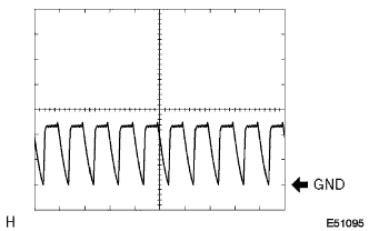
Using an oscilloscope, check waveform 1.
Waveform 1 (Reference) Item Content Terminal No. (Symbols)
-
CH: 1 L169-9 (SOF) - L169-19 (E1)
-
CH: 2 L169-24 (SOR) - L169-18 (E2)
Tool Setting 2 V/DIV., 1 msec./DIV. Condition Engine switch on (IG), clearance sonar main switch ON. -
-
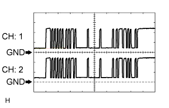
Using an oscilloscope, check waveform 2.
Waveform 2 (Reference) Item Content Terminal No. (Symbols)
-
L169-1 (CBZ) - L169-17 (E)
-
L169-2 (EE) - L169-17 (E)
-
L169-11 (EF) - L169-17 (E)
Tool Setting 5 V/DIV., 1 msec./DIV. Condition Engine switch on (IG), clearance sonar main switch ON, shift lever in R position and sensor is in detecting state Note
-
The waveforms of CBZ and EE are offset by a half cycle. EF is not synchronized with CBZ and EE.
-
The waveform's amplitude varies depending on the volume setting.
-
-