NAVIGATION SYSTEM TERMINALS OF ECU

-
MULTI-MEDIA MODULE RECEIVER ASSEMBLY
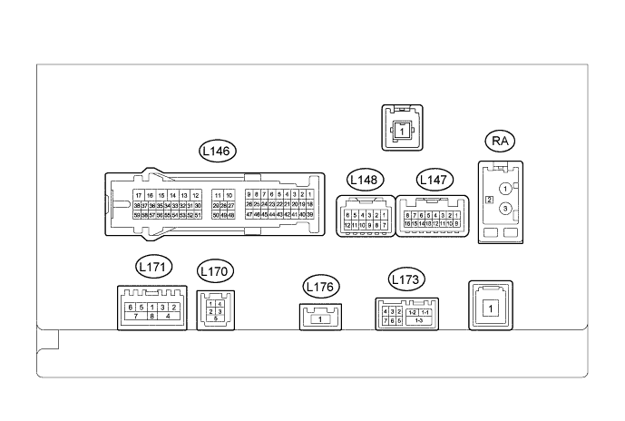
Terminal No. (Symbol) Wiring Color Terminal Description Condition Specified Condition L148-7 (GND2) - L146-12 (GND1) G - W-B Ground Always Below 1 V L148-11 (ACC) - L146-12 (GND1) V - W-B Power source (ACC) Engine switch on (ACC) 11 to 14 V Engine switch off Below 1 V L148-12 (+B) - L146-12 (GND1) R - W-B Power source Always 11 to 14 V L146-1 (CANH) R CAN communication signal - - L146-2 (CANL) G CAN communication signal - - L146-3 (CNH1) W Local Bus communication signal - - L146-4 (CNL1) B Local Bus communication signal - - L146-10 (VMTF) - L146-12 (GND1) R - W-B Visual mute signal When image on display switches 3.5 V or higher → Below 1 V → 3.5 V or higher L146-12 (GND1) - Body ground W-B - Body ground Ground Always Below 1 Ω L146-13 (ILL-) - L146-12 (GND1) LG - W-B Illumination signal Engine switch on (IG), light control switch off → tail or head (Light intensity is not max. or min.) Below 1 V → Pulse generation L146-14 (ILL+) - L146-12 (GND1) G - W-B Illumination signal Engine switch on (IG), light control switch off → tail or head position Below 1 V → 11 to 14 V L146-15 (IG) - L146-12 (GND1) V - W-B Power source (IG) Engine switch on (IG) 11 to 14 V Engine switch off Below 1 V L146-16 (ACC1) - L146-12 (GND1) LG - W-B Power source (ACC) Engine switch on (ACC) 11 to 14 V Engine switch off Below 1 V L146-17 (+B1) - L146-12 (GND1) R - W-B Power source Always 11 to 14 V L146-18 (V+) - L146-12 (GND1) W - W-B Television camera image signal Engine switch on (IG), reverse (R) selected, camera lens not covered, displaying an image Pulse generation (Refer to waveform 1) Engine switch on (IG), reverse (R) selected, camera lens covered, blacking out screen Pulse generation (Refer to waveform 2) L146-19 (V-) - L146-12 (GND1) R - W-B Ground Always Below 1 V L146-27 (MIN+) - L146-12 (GND1) Y - W-B*1
W - W-B*2
Microphone voice signal See "Microphone & Voice Recognition Check" in Operation Check Click here
- L146-28 (SGND) - L146-12 (GND1) Shielded - W-B Shield ground Always Below 1 V L146-29 (MACC) - L146-12 (GND1)*2 B - W-B Telephone microphone assembly power supply Engine switch off Below 1 V Engine switch on (ACC) 4 to 6 V L146-30 (SW1) - L146-32 (SWG) BR - B Steering pad switch signal Steering pad switch not operated 4.44 to 5.43 V Seek+ switch pushed 0.45 to 0.65 V Seek- switch pushed 1.19 to 1.49 V Vol+ switch pushed 2.09 to 2.54 V Vol- switch pushed 3.2 to 3.88 V L146-31 (SW2) - L146-32 (SWG) G - B Steering pad switch signal Steering pad switch not operated 4.44 to 5.43 V MODE switch pushed 0.45 to 0.65 V On hook switch pushed 1.19 to 1.49 V Off hook switch pushed 2.09 to 2.54 V Voice switch pushed 3.2 to 3.88 V L146-32 (SWG) - Body ground B - Body ground Steering pad switch signal Always Below 1 V L146-39 (CA+) - L146-12 (GND1) B - W-B Television camera power supply Engine switch on (IG), reverse (R) selected 5.5 to 7.05 V L146-40 (CGND) - Body ground Shielded - Body ground Shield ground Always Below 1 V L146-45 (TX3+) R AVC-LAN communication signal - - L146-46 (TX3-) G AVC-LAN communication signal - - L146-48 (MIN-) - Body ground BR - Body ground*1
R - Body ground*2
Microphone voice signal See "Microphone & Voice Recognition Check" in Operation Check Click here
- L146-49 (SNS2) - L146-12 (GND1) BE - W-B Microphone connection detection signal Always Below 1 V L146-56 (SPD) - L146-12 (GND1) V - W-B Speed signal from No. 1 meter ECU sub-assembly See "Vehicle Signal Check Mode" in Operation Check Click here
- L146-57 (REV) - L146-12 (GND1) R - W-B Receiver signal See "Vehicle Signal Check Mode" in Operation Check Click here
- L147-1 (NTSO) - L146-12 (GND1)*3 R - W-B Display signal RSE playing A waveform synchronized with sound is output. L147-2 (NTSG) - L146-12 (GND1)*3 G - W-B Display signal ground Always Below 1 V L147-3 (SLD2) - L146-12 (GND1)*3 Shielded - W-B Shielded ground Always Below 1 V L147-4 (VMTR) - L146-12 (GND1)*3 BE - W-B Mute signal RES playing → Source changed 4 V or higher → Below 0.7 V → 4 V or higher L147-5 (AGND) - Body ground Shielded - Body ground Shield ground Always Below 1 V L147-7 (VAR+) - L147-15 (VA-) W - R Sound signal (Right) AUX audio device playing (When stereo jack adapter used) A waveform synchronized with sound is output. L147-8 (VAL+) - L147-15 (VA-) B - R Sound signal (Left) AUX audio device playing (When stereo jack adapter used) A waveform synchronized with sound is output. L147-15 (VA-) - L146-12 (GND1) R - W-B Sound signal ground Always Below 1 V L147-16 (ADPG) - L146-12 (GND1) BR - W-B External device connector detection signal External device connected Below 1 V External device not connected 2.1 to 3 V L173-1-1 (USB-)*1 W USB communication line - - L173-1-2 (USB+)*1 W USB communication line - - L173-1-3 (USBS) - Body ground*1 W - Body ground Shield ground Always Below 1 V L173-2 (USBG) - Body ground*1 W - Body ground Shield ground Always Below 1 V L173-3 (VOT+) - L146-12 (GND1)*1 W - W-B Sent voice signal Destination assist service in use and vehicle occupant speaking to operator A waveform synchronized with the sent voice is output. L173-4 (USBV) - L146-12 (GND1)*1 W - W-B DCM (Telematics transceiver) power supply Engine switch on (ACC) 4.75 to 5.25 V Engine switch off Below 1 V L173-5 (VOT-) - L146-12 (GND1)*1 R - W-B Sent voice signal Destination assist service in use and vehicle occupant speaking to operator A waveform synchronized with the sent voice is output. L173-6 (VOR-) - L146-12 (GND1)*1 B - W-B Receive voice signal Destination assist service in use and operator speaking to vehicle occupant A waveform synchronized with the received voice is output. L173-7 (VOR+) - L146-12 (GND1)*1 G - W-B Receive voice signal Destination assist service in use and operator speaking to vehicle occupant A waveform synchronized with the received voice is output. L170-1 (USV1) R Power source - - L170-2 (US1-) V Data signal - - L170-3 (US1+) BR Data signal - - L170-4 (UGD1) B Ground - - L170-5 (USG1) Shielded Shield ground - - L171-1 (WUO) - L146-12 (GND1) W - W-B MOST communication signal Engine switch on (ACC) 4.5 V or higher Engine switch off Below 1 V L171-2 (MI+) B MOST communication signal - - L171-3 (MI-) B MOST communication signal - - L171-4 (SLDI) - L146-12 (GND1) Shielded - W-B Shield ground Always Below 1 V L171-5 (MO+) B MOST communication signal - - L171-6 (MO-) B MOST communication signal - - L171-7 (SLDO) - L146-12 (GND1) Shielded - W-B Shield ground Always Below 1 V
-
*1: w/ Emergency Call Switch
-
*2: w/o Emergency Call Switch
-
*3: w/ Rear Seat Entertainment System
-
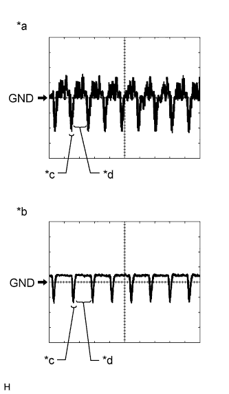
Text in Illustration *a Waveform 1 (camera lens is not covered, displaying an image) *b Waveform 2 (camera lens is covered, blacking out the screen) *c Synchronization Signal *d Video Waveform Reference (Oscilloscope waveform):
-
Waveform 1 (camera lens is not covered, displaying an image)
Item Content Measurement terminal L146-18 (V+) - L146-12 (GND1) Measurement setting 200 mV/DIV., 50 μs/DIV. Condition Engine switch on (IG), reverse (R) selected, camera lens is not covered, displaying an image Tech Tips
The video waveform changes according to the image from the television camera assembly.
-
Waveform 2 (camera lens is covered, blacking out the screen)
Item Content Measurement terminal L146-18 (V+) - L146-12 (GND1) Measurement setting 200 mV/DIV., 50 μs/DIV. Condition Engine switch on (IG), reverse (R) selected, camera lens is covered, blacking out screen Tech Tips
The video waveform changes according to the image from the television camera assembly.
-
-
-
ACCESSORY METER ASSEMBLY
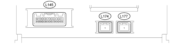
Terminal No. (Symbol) Wiring Color Terminal Description Condition Specified Condition L145-2 (ILL+) - L145-13 (GND1) G - W-B Illumination signal Engine switch on (IG), light control switch off → tail or head position Below 1 V → 11 to 14 V L145-5 (TX2+) G AVC-LAN communication signal - - L145-6 (TX1+) R AVC-LAN communication signal - - L145-7 (TX+) R AVC-LAN communication signal - - L145-11 (VMT1) - L145-13 (GND1) R - W-B Visual mute signal When image on display switches 3.5 V or higher → Below 1 V → 3.5 V or higher L145-12 (+B2) - L145-13 (GND1) R - W-B Power source Always 11 to 14 V L145-13 (GND1) - Body ground W-B - Body ground Ground Always Below 1 Ω L145-15 (WUI) P Local Bus communication signal - - L145-16 (WUO) Y Local Bus communication signal - - L145-17 (TX2-) R AVC-LAN communication signal - - L145-18 (TX1-) BR AVC-LAN communication signal - - L145-19 (TX-) G AVC-LAN communication signal - - L145-23 (IG) - L145-13 (GND1) V - W-B Power source (IG) Engine switch on (IG) 11 to 14 V Engine switch off Below 1 V L145-24 (ACC) - L145-13 (GND1) LG - W-B Power source (ACC) Engine switch on (ACC) 11 to 14 V Engine switch off Below 1 V -
REMOTE TOUCH
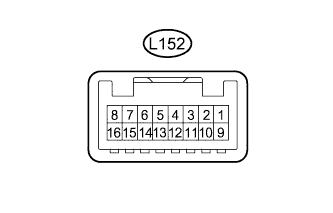
Terminal No. (Symbol) Wiring Color Terminal Description Condition Specified Condition L152-1 (+B) - L152-15 (GND) L - W-B Power source Always 11 to 14 V L152-2 (ACC) - L152-15 (GND) G - W-B Power source (ACC) Engine switch on (ACC) 11 to 14 V Engine switch off Below 1 V L152-4 (MO-) B Local Bus communication signal - - L152-5 (MO+) W Local Bus communication signal - - L152-9 (ILL+) - L152-15 (GND) R - W-B Illumination signal Engine switch on (IG), light control switch off → tail or head position Below 1 V → 11 to 14 V L152-12 (MI-) P Local Bus communication signal - - L152-13 (MI+) Y Local Bus communication signal - - L152-15 (GND) - Body ground W-B - Body ground Ground Always Below 1 V L152-16 (ILL-) - L152-15 (GND) W - W-B Illumination signal Engine switch on (IG), light control switch off → tail or head position (Light intensity is not max. or min.) Below 1 V → Pulse generation -
CLOCK ASSEMBLY

Terminal No. (Symbol) Wiring Color Terminal Description Condition Specified Condition L143-2 (TX-1) R AVC-LAN communication signal - - L143-3 (TX+1) G AVC-LAN communication signal - - L143-5 (B) - L143-7 (E) R - W-B Power source Always 11 to 14 V L143-7 (E) - Body ground W-B - Body ground Ground Always Below 1 V L143-10 (ACC) - L143-7 (E) LG - W-B Power source (ACC) Engine switch on (ACC) 11 to 14 V -
STEREO COMPONENT AMPLIFIER ASSEMBLY Click here
-
DCM (TELEMATICS TRANSCEIVER) (w/ Emergency Call Switch) Click here