INSTRUMENT PANEL SPEAKER REMOVAL

Tech Tips
-
Use the same procedure for the RH and LH sides.
-
The procedure listed below is for the LH side.
-
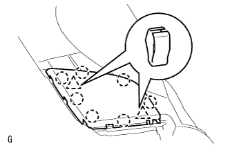
REMOVE NO. 1 SPEAKER HOLE COVER
-
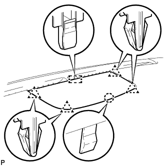
Detach the 4 clips, claw and clamp and remove the No. 1 speaker hole cover.
-
-
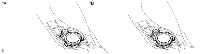
REMOVE FRONT NO. 3 SPEAKER ASSEMBLY
-
Remove the 2 bolts.
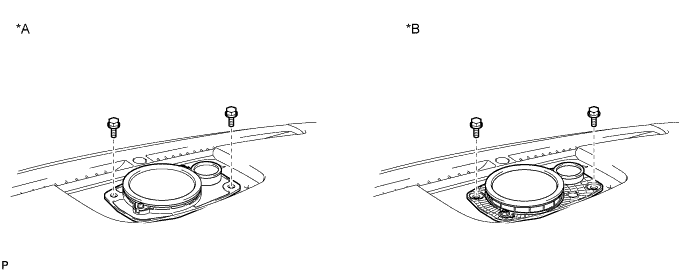
Text in Illustration *A for Standard *B for 19 Speaker -
Disconnect the connector and remove the front No. 3 speaker assembly.
Note
Do not touch the cone of the speaker.
-
-
REMOVE FRONT PILLAR GARNISH LH

Text in Illustration *1 Front Pillar Garnish Clip
-
Pull the upper part of the front pillar garnish LH toward the inside of the cabin and detach the 2 clips.
Tech Tips
Make the front pillar garnish LH hang down from the front pillar garnish clip.
-
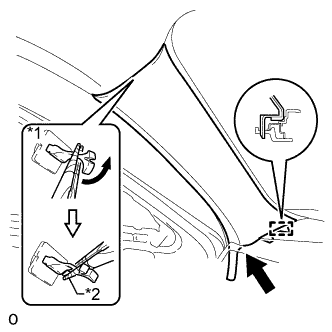
Text in Illustration *1 Front Pillar Garnish Clip *2 Protective Tape Turn the end of the front pillar garnish clip 90° with needle-nose pliers and remove it from the front pillar garnish LH.
Note
-
Front pillar garnish clips are reusable if they are not removed from the vehicle and have no damage.
-
Replace the front pillar garnish clips with new ones if they are removed from the vehicle.
Tech Tips
Tape the tips of the needle-nose pliers before use.
-
-
Pull the front pillar garnish LH to detach the guide and remove it.
-
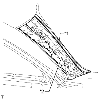
Text in Illustration *1 Adhesive Tape *2 Protective Cover Protect the curtain shield airbag assembly LH.
Completely cover the curtain shield airbag assembly LH with a cloth or nylon sheet and secure the ends of the cover with adhesive tape as shown in the illustration.
Note
Cover the curtain shield airbag assembly LH with a protective cover as soon as the front pillar garnish LH is removed.
-
-
REMOVE NO. 1 INSTRUMENT PANEL SPEAKER PANEL SUB-ASSEMBLY
-
Detach the 2 clips and 7 claws.
-
Remove the No. 1 instrument panel speaker panel sub-assembly.
-
-
REMOVE FRONT NO. 2 SPEAKER ASSEMBLY
-
Remove the 2 bolts.
Text in Illustration *A for Standard *B for 19 Speaker -
Disconnect the connector and remove the front No. 2 speaker assembly.
Note
Do not touch the cone of the speaker.
-