REAR SEAT ENTERTAINMENT SYSTEM Display Signal Circuit between Radio Receiver and Television Display Assembly
DESCRIPTION
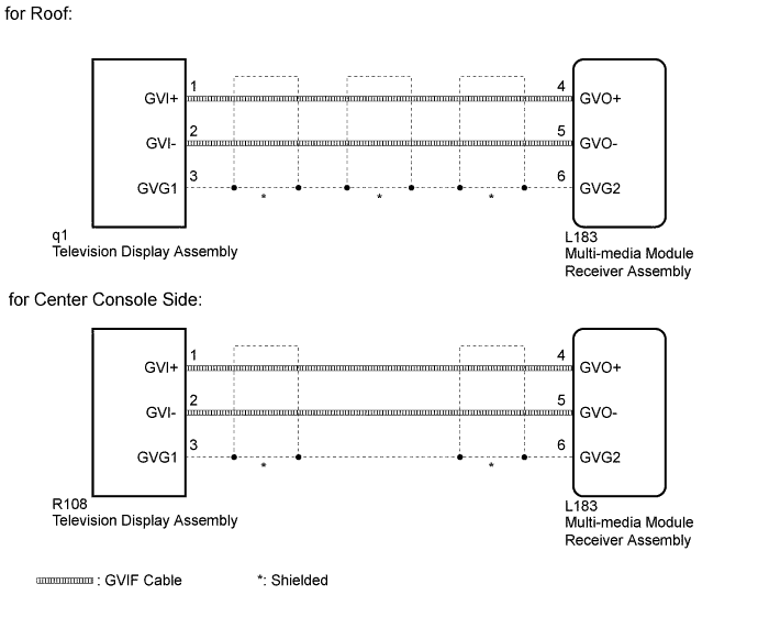
This is the display signal circuit between the multi-media module receiver assembly and the television display assembly.
WIRING DIAGRAM
INSPECTION PROCEDURE
PROCEDURE
-
CHECK HARNESS AND CONNECTOR (GVIF CABLE)
-
Check if the GVIF cable connectors between the multi-media module receiver assembly and the accessory meter assembly have any connection problems Click here.
NG 
REMOVE CONNECTION PROBLEMS (GVIF CABLE)
OK 
-
-
CHECK HARNESS AND CONNECTOR (MULTI-MEDIA MODULE RECEIVER ASSEMBLY - TELEVISION DISPLAY ASSEMBLY)
-
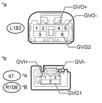
Text in Illustration *A for Roof *B for Center Console Side *a GVIF Cable
(to Multi-media Module Receiver Assembly)
*b GVIF Cable
(to Television Display Assembly)
Remove the GVIF cable from the multi-media module receiver assembly and accessory meter assembly.
-
Measure the resistance according to the value(s) in the table below.
Standard Resistance for Roof Tester Connection Condition Specified Condition L183-4 (GVO+) - q1-1 (GVI+) Always Below 1 Ω L183-5 (GVO-) - q1-2 (GVI-) Always Below 1 Ω L183-6 (GVG2) - q1-3 (GVG1) Always Below 1 Ω L183-4 (GVO+) or q1-1 (GVI+) - Body ground Always 10 kΩ or higher L183-5 (GVO-) or q1-2 (GVI-) - Body ground Always 10 kΩ or higher L183-6 (GVG2) or q1-3 (GVG1) - Body ground Always 10 kΩ or higher for Center Console Side Tester Connection Condition Specified Condition L183-4 (GVO+) - R108-1 (GVI+) Always Below 1 Ω L183-5 (GVO-) - R108-2 (GVI-) Always Below 1 Ω L183-6 (GVG2) - R108-3 (GVG1) Always Below 1 Ω L183-4 (GVO+) or R108-1 (GVI+) - Body ground Always 10 kΩ or higher L183-5 (GVO-) or R108-2 (GVI-) - Body ground Always 10 kΩ or higher L183-6 (GVG2) or R108-3 (GVG1) - Body ground Always 10 kΩ or higher
NG
REPLACE HARNESS AND CONNECTOR (GVIF CABLE)
OK 
PROCEED TO NEXT SUSPECTED AREA SHOWN IN PROBLEM SYMPTOMS TABLE Click here
-