AUDIO AND VISUAL SYSTEM Display Signal Circuit between Multi-display and Radio Receiver
DESCRIPTION
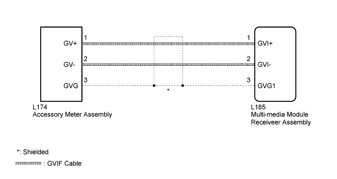
The display image signal from the multi-media module receiver assembly is sent to the accessory meter assembly using a digital communication cable.
WIRING DIAGRAM
INSPECTION PROCEDURE
PROCEDURE
-
CHECK HARNESS AND CONNECTOR (GVIF CABLE)
-
Check if the digital communication cable connectors between the multi-media module receiver assembly and the accessory meter assembly have any connection problems Click here.
-
Check that the screen display is normal.
OK Screen display is normal.
NG 
REMOVE CONNECTION PROBLEM (GVIF CABLE)
OK 
CHECK HARNESS AND CONNECTOR (GVIF CABLE)
-
-
CHECK HARNESS AND CONNECTOR (GVIF CABLE)
-
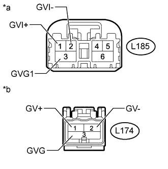
Text in Illustration *a GVIF Cable
(to Multi-media Module Receiver Assembly)
*b GVIF Cable
(to Accessory Meter Assembly)
Remove the GVIF cable from the multi-media module receiver assembly and accessory meter assembly.
-
Measure the resistance according to the value(s) in the table below.
Standard Resistance Tester Connection Condition Specified Condition L182-1 (GVI+) - L164-1 (GV+) Always Below 1 Ω L182-2 (GVI-) - L164-2 (GV-) Always Below 1 Ω L182-3 (GVG1) - L164-3 (GVG) Always Below 1 Ω L182-1 (GVI+) or L164-1 (GV+) - Body ground Always 10 kΩ or higher L182-2 (GVI-) or L164-2 (GV-) - Body ground Always 10 kΩ or higher L182-3 (GVG1) or L164-3 (GVG) - Body ground Always 10 kΩ or higher
NG
REPLACE HARNESS AND CONNECTOR (GVIF CABLE)
OK 
-
-
CHECK ACCESSORY METER ASSEMBLY
-
Replace the accessory meter assembly with a new or known good one Click here.
-
Check that the screen display is normal.
OK Screen display is normal.
NG
PROCEED TO NEXT SUSPECTED AREA SHOWN IN PROBLEM SYMPTOMS TABLE Click here
OK
END (ACCESSORY METER ASSEMBLY IS DEFECTIVE)
-