METER / GAUGE SYSTEM Odo / Trip Switch Malfunction
DESCRIPTION
The meter's ODO / TRIP display changes each time the trip switch is pressed.
Tech Tips
For more information about changing between displays, refer to the owner's manual.
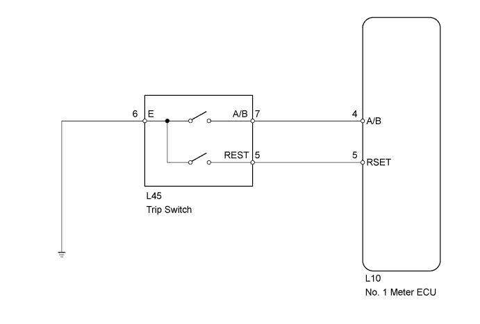
WIRING DIAGRAM
INSPECTION PROCEDURE
PROCEDURE
-
READ VALUE USING INTELLIGENT TESTER (TRIP SWITCH)
-
Operate the intelligent tester according to the display and select "Data List".
Combination Meter: Tester Display Measurement Item/Range Normal Condition Diagnostic Note ODO/TRIP Change SW Trip switch (ODO/TRIP switch) condition/ON or OFF ON: Switch is pushed
OFF: Switch is not pushed
- Trip Reset SW Trip switch (RESET switch) condition/ON or OFF ON: Trip switch (ODO/TRIP switch) pushed
OFF: Trip switch (ODO/TRIP switch) not pushed
- OK Switch condition (ON/OFF) can be switched by actual operation.
NG 
INSPECT TRIP SWITCH Click here
OK 
REPLACE NO. 1 METER ECU
-
-
INSPECT TRIP SWITCH
-
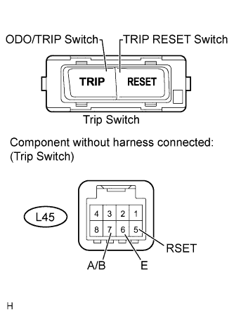
Remove the trip switch Click here.
-
Measure the resistance according to the value(s) in the table below.
Standard resistance Tester Connection Switch Condition Specified Condition 5 (RSET) - 6 (E) RESET switch ON (Pushed) Below 1 Ω RESET switch OFF (Not pushed) 10 kΩ or higher 7 (A/B) - 6 (E) ODO/TRIP switch ON (Pushed) Below 1 Ω ODO/TRIP switch OFF (Not pushed) 10 kΩ or higher
NG 
REPLACE TRIP SWITCH Click here
OK 
-
-
CHECK HARNESS AND CONNECTOR (NO. 1 METER ECU - TRIP SWITCH AND BODY GROUND)
-
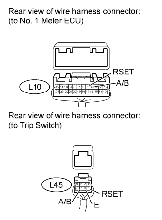
Disconnect the L10 meter connector.
-
Disconnect the L45 switch connector.
-
Measure the resistance according to the value(s) in the table below.
Standard resistance Tester Connection Condition Specified Condition L10-4 (A/B) - L45-7 (A/B) Always Below 1 Ω L10-5 (RSET) - L45-5 (RSET) L45-6 (E) - Body ground L10-4 (A/B) or L45-7 (A/B) - Body ground Always 10 kΩ or higher L10-5 (RSET) or L45-5 (RSET) - Body ground
NG
REPAIR OR REPLACE HARNESS OR CONNECTOR
OK
REPLACE NO. 1 METER ECU
-