METER / GAUGE SYSTEM TERMINALS OF ECU

-
CHECK NO. 1 METER ECU

-
Measure the resistance and voltage according to the value(s) in the table below.
Terminal No. (Symbols) Wiring Color Terminal Description Condition Specified Condition L10-1 (B) - Body ground G - Body ground Turn indicator light LH signal Engine switch on (IG), turn indicator light LH off Below 1 V Engine switch on (IG), turn indicator light LH blinks Alternating between below 1 and 11 to 14 V L10-4 (A/B) - Body ground B - Body ground ODO/TRIP switch signal Engine switch on (IG), ODO/TRIP switch on Below 1 V Engine switch on (IG), ODO/TRIP switch off 4.4 to 5.5 V L10-5 (RSET) - Body ground BR - Body ground RESET switch signal Engine switch on (IG), RESET switch on Below 1 V Engine switch on (IG), RESET switch off 4.4 to 5.5 V L10-7 (RHDW) - Body ground L - Body ground Light control rheostat DOWN switch signal Engine switch on (IG), Light control rheostat DOWN switch on Below 1 V Engine switch on (IG), Light control rheostat DOWN switch off 4.4 to 5.5 V L10-8 (RHUP) - Body ground R - Body ground Light control rheostat UP switch signal Engine switch on (IG), Light control rheostat UP switch on Below 1 V Engine switch on (IG), Light control rheostat UP switch off 4.4 to 5.5 V L10-9 (SI) - Body ground L - Body ground Speed signal (Input) Engine switch on (IG) and turn the wheel slowly Pulse generation (See waveform) L10-10 (+S) - Body ground V - Body ground Speed signal (Output) Engine switch on (IG) and turn the wheel slowly Pulse generation (See waveform) L10-11 (EFI) - Body ground R - Body ground MIL MIL on Below 1 to 4.2 V MIL off 11 to 14 V L10-12 (B) - Body ground Y - Body ground Turn indicator light RH signal Engine switch on (IG), turn indicator light RH off Below 1 V Engine switch on (IG), turn indicator light RH blinks Alternating between below 1 and 11 to 14 V L10-13 (B) - Body ground P - Body ground +B power supply Always 11 to 14 V L10-14 (IG2) - Body ground L - Body ground IG power supply Engine switch off Below 1 V Engine switch on (IG) 11 to 14 V L10-16 (ILL-) - Body ground LG - Body ground Illumination signal Engine switch on (IG) Pulse generation L10-17 (E2) - Body ground W-B - Body ground Ground (Power ground) Always Below 1 Ω L10-18 (ES) - Body ground BR - Body ground Ground Always Below 1 Ω L10-24 (EPB*) - Body ground L - Body ground Parking brake switch signal Engine switch on (IG), parking brake switch on Below 1.5 V Engine switch on (IG), parking brake switch off 11 to 14 V
-
EPB*: Electric Parking Brake System
-
-
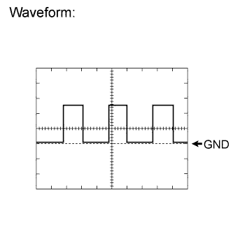
Using an oscilloscope, check the waveform.
Waveform (Reference) Item Condition Terminal No. (Symbols) L10-10 (+S) - Body ground
L10-9 (SI) - Body ground
Tool setting 5 V/DIV., 20 msec./DIV. Vehicle condition Engine switch on (IG) and turn the wheel slowly
Driving at approximately 20 km/h (12 mph)
Tech Tips
As vehicle speed increases, the cycle of the signal waveform narrows.
-
-
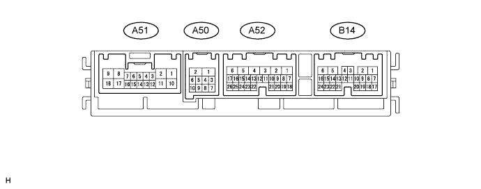
FRONT MULTIPLEX NETWORK LIGHT ECU (FRONT CONTROLLER)
-
Disconnect the A50 and A52 front controller connectors.
-
Measure the resistance and voltage according to the value(s) in the table below.
Terminal No. (Symbols) Wiring Color Terminal Description Condition Specified Condition A52-5 (ALTB) - Body ground L - Body ground +B power supply Always 11 to 14 V A52-1 (BATB) - Body ground P - Body ground +B power supply Always 11 to 14 V A50-1 (FMB3) - Body ground LG - Body ground +B power supply Always 11 to 14 V A50-5 (FMIG) - Body ground Y - Body ground IG power supply Engine switch off Below 1 V Engine switch on (IG) 11 to 14 V A50-2 (E) - Body ground W-B - Body ground Ground Always Below 1 Ω -
Reconnect the A50 and A52 front controller connectors.
-
Measure the voltage according to the value(s) in the table below.
Terminal No. (Symbols) Wiring Color Terminal Description Condition Specified Condition A52-10 (MOL) - A52-20 (MOLE) L - W Engine oil level sensor signal Engine oil level sensor on Below 1 V Engine oil level sensor off 11 to 14 V A52-11 (MOPS) - Body ground R - Body ground Engine oil pressure switch signal Engine switch on (IG), engine oil pressure warning display on Below 1 V Engine switch on (IG), engine oil pressure warning display off 11 to 14 V A52-12 (ALTL) - Body ground P - Body ground Charge warning light signal Engine switch on (IG), charge warning light on Below 1 V Engine switch on (IG), charge warning light off 11 to 14 V
-
-
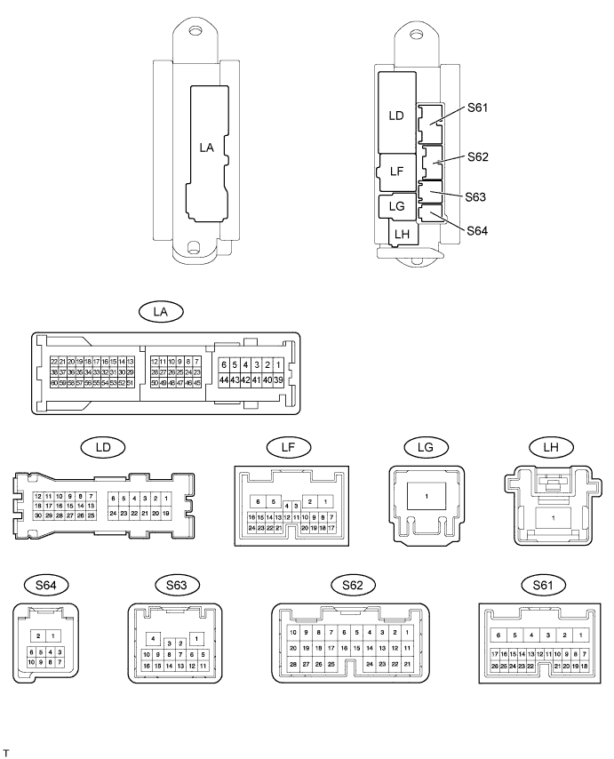
CHECK LUGGAGE ROOM JUNCTION BLOCK (REAR JUNCTION BLOCK ECU)
-
Disconnect the LA, LD and LG luggage room junction block connectors.
-
Measure the resistance and voltage according to the value(s) in the table below.
Terminal No. (Symbol) Wiring Color Terminal Description Condition Specified Condition LA-29 (SG) - Body ground W-B - Body ground Ground Always Below 1 Ω LA-43 (PGND) - Body ground W-B - Body ground Ground Always Below 1 Ω LD-4 (MPXB) - LA-29 (SG) R - W-B ECU power supply Always 11 to 14 V LG-1 (FUEL) - LA-29 (SG) W - W-B*1
R - W-B*2
+B power supply Always 11 to 14 V
-
If the result is not as specified, there may be a malfunction on the wire harness side.
-
*1: w/ Pre-crash Safety System
-
*2: w/o Pre-crash Safety System
-
-
Reconnect the LA, LD and LG luggage room junction block connectors.
-
Measure the resistance and voltage according to the value(s) in the table below.
Terminal No. (Symbol) Wiring Color Terminal Description Condition Specified Condition S61-7 (FR) - Body ground SB - Body ground Fuel level signal Engine switch on (IG), fuel level F Below 1 V Engine switch on (IG), fuel level E 4.5 to 9 V S61-18 (FE) - Body ground LG - Body ground Ground (Fuel ground) Always Below 1 Ω
-
-
CHECK STEERING PAD SWITCH
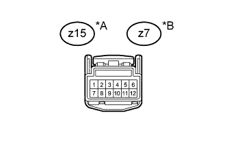
Text in Illustration *A w/ Transmission Shift Switch *B w/o Transmission Shift Switch
-
Measure the voltage according to the value(s) in the table below.
Terminal No. (Symbols) Wiring Color Terminal Description Condition Specified Condition z15-12 - Body ground*1 W - Body ground +B power supply Always 11 to 14 V z7-12 - Body ground*2 R - Body ground +B power supply Always 11 to 14 V
-
*1: w/ Transmission Shift Switch
-
*2: w/o Transmission Shift Switch
-
-