FRONT DOOR LOCK INSTALLATION

Tech Tips
-
Use the same procedures for the LH side and RH side.
-
The procedures listed below are for the LH side.
-
INSTALL FRONT DOOR INSIDE LOCKING CABLE ASSEMBLY LH
-
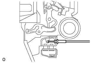
Install the front door inside locking cable assembly LH.
-
Attach the 3 claws.
-
-
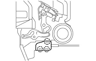
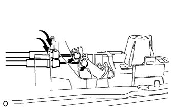
INSTALL FRONT DOOR LOCK REMOTE CONTROL CABLE ASSEMBLY LH
-
Install the front door lock remote control cable assembly LH.
-
Attach the claw.
-
-
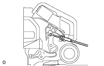
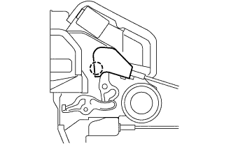
INSTALL FRONT DOOR LOCK ASSEMBLY LH
-
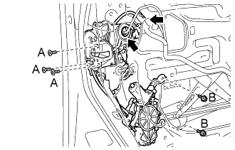
Apply adhesive to the threads of the 5 screws.
Adhesive Toyota Genuine Adhesive 1324, Three Bond 1324 or equivalent -
Install the front door lock assembly LH.
-
Using a T30 ''TORX'' wrench, install the 3 screws labeled A and the 2 screws labeled B.
- Torque:
- 5.5 N*m { 56 kgf*cm, 49 in.*lbf }
-
Connect the 2 connectors.
-
-
INSTALL FRONT DOOR LOWER FRAME GARNISH PAD LH
-
Install the front door lower frame garnish pad LH with the 2 bolts.
-
-
INSTALL FRONT DOOR OUTSIDE HANDLE COVER LH
-
Using a T30 ''TORX'' socket, install the front door outside handle cover LH (with the door key cylinder) with the screw.
- Torque:
- 4.0 N*m { 41 kgf*cm, 35 in.*lbf }
-
Install the hole plug.
-
-
INSTALL FRONT DOOR FRAME SUB-ASSEMBLY REAR LOWER LH
-
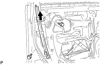
Install the front door rear lower frame sub-assembly LH with the 2 bolts.
- Torque:
- 8.0 N*m { 82 kgf*cm, 71 in.*lbf }
-
-
INSTALL FRONT DOOR GLASS SUB-ASSEMBLY LH
-
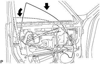
Insert the front door glass sub-assembly LH into the door panel along the glass run as indicated by the arrows in the illustration.
Note
Be careful not to damage the glass.
-
Install the front door glass sub-assembly LH to the front door window regulator sub-assembly LH with the 2 bolts.
- Torque:
- 5.5 N*m { 56 kgf*cm, 49 in.*lbf }
-
Install the hole plug.
-
-
INSTALL FRONT DOOR SERVICE HOLE COVER LH
-
Apply new butyl tape to the door.
-
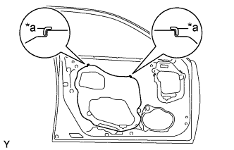
Text in Illustration *a Reference Point Install a new front door service hole cover LH using the reference points on the front door panel.
Tech Tips
-
When installing the service hole cover, pull the links and connectors through the service hole cover.
-
There should be no wrinkles or folds after attaching the service hole cover.
-
After attaching the service hole cover, check the sealing quality.
-
-
-
INSTALL FRONT DOOR TRIM COVER LH
-
Attach the 5 clips to install the front door trim cover LH.
-
Install the cushion.
-
-
INSTALL FRONT DOOR TRIM BOARD SUB-ASSEMBLY LH
-
Connect the connector.
-
Connect the 2 cables to the inside handle.
-
Attach the 13 clips to install the front door trim board sub-assembly LH.
-
Install the 3 screws.
-
-
INSTALL POWER WINDOW REGULATOR MASTER SWITCH ASSEMBLY WITH FRONT DOOR ARMREST BASE PANEL
-
INSTALL DOOR INSIDE HANDLE BEZEL
-
Attach the 3 claws to install the front door inside handle bezel plug LH.
-
-
CONNECT CABLE TO NEGATIVE BATTERY TERMINAL
Note
When disconnecting the cable, some systems need to be initialized after the cable is reconnected Click here.
-
INSTALL COWL TOP VENTILATOR LOUVER RH
-

Install the 6 clips and cowl top ventilator louver RH.
Note
Be sure to install the cowl top ventilator louver RH properly. If it is not installed properly, water may enter the engine room and cause malfunctions.
-