ENTRY AND START SYSTEM Driver Side Door Entry Lock Function does not Operate
DESCRIPTION
If the driver door entry lock function does not operate but the entry unlock operation operates, the communication line between the vehicle and electrical key transmitter is normal. Either of the following may have occurred: 1) the entry lock switch is malfunctioning; or 2) the front door ECU (for driver side) receives the entry lock switch ON signal, but is unable to send the signal to the certification ECU through CAN communication.
WIRING DIAGRAM
Refer to Driver Side Door Entry Lock and Unlock Functions do not Operate Click here.
INSPECTION PROCEDURE
PROCEDURE
-
CHECK POWER DOOR LOCK OPERATION
-
When the master switch assembly's door control switch is operated, check that the locked doors unlock.
Result Result Proceed to Door locks operate normally OK Door locks do not operate normally NG
NG 
GO TO POWER DOOR LOCK CONTROL SYSTEM Click here
OK 
-
-
READ VALUE USING INTELLIGENT TESTER (DOOR LOCK POSITION SWITCH)
-
Using the intelligent tester, read the Data List.
Driver Door (Front door ECU LH*1) (Front door ECU RH*2) Tester Display Measurement Item/Display Normal Condition Diagnostic Note Lock Position SW Driver side door lock position switch signal / ON or OFF ON: Driver side door is unlocked
OFF: Driver side door is locked
- Tech Tips
*1: for LHD
*2: for RHD
OK On intelligent tester screen, item changes between ON and OFF according to above chart.
NG
GO TO POWER DOOR LOCK CONTROL SYSTEM (Proceed to Only Driver Door LOCK/UNLOCK Functions do not Operate) Click here
OK
-
-
READ VALUE USING INTELLIGENT TESTER (OUTSIDE HANDLE)
-
Using the intelligent tester, read the Data List.
Driver Door (Front door ECU LH*1) (Front door ECU RH*2) Tester Display Measurement Item/Display Normal Condition Diagnostic Note Outside Handle Trigger SW Driver side door outside handle lock switch / ON or OFF ON: Driver side door outside handle lock switch is pushed
OFF: Driver side door outside handle lock switch is not pushed
- Tech Tips
*1: for LHD
*2: for RHD
OK On intelligent tester screen, item changes between ON and OFF according to above chart.
NG 
INSPECT FRONT DOOR OUTSIDE HANDLE (for Driver Side) Click here
OK
-
-
CHECK FRONT DOOR ECU (OPERATION)
-
Replace the front door ECU LH*1 or RH*2 with a new one or normally functioning one Click here.
Tech Tips
*1: for LHD
*2: for RHD
-
Check that the entry function operates normally.
OK Operates normally
NG
REPLACE CERTIFICATION ECU
OK 
END (FRONT DOOR ECU IS DEFECTIVE)
-
-
INSPECT FRONT DOOR OUTSIDE HANDLE (for Driver Side)
-
Remove the front door outside handle.
-
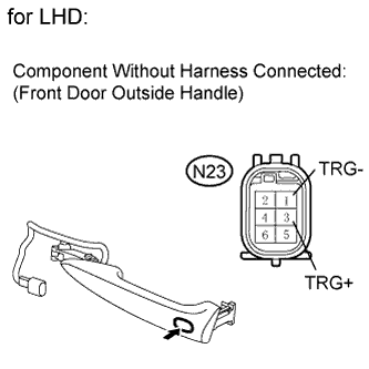
for LHD:
-
Measure the resistance according to the value(s) in the table below.
Standard resistance Tester Connection Switch Condition Specified Condition N23-3 (TRG+) - N23-1 (TRG-) ON Below 1 Ω N23-3 (TRG+) - N23-1 (TRG-) OFF 10 kΩ or higher
-
-
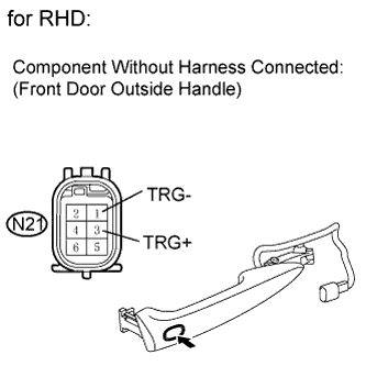
for RHD:
-
Measure the resistance according to the value(s) in the table below.
Standard resistance Tester Connection Switch Condition Specified Condition N21-3 (TRG+) - N21-1 (TRG-) ON Below 1 Ω N21-3 (TRG+) - N21-1 (TRG-) OFF 10 kΩ or higher
-
NG
REPLACE FRONT DOOR OUTSIDE HANDLE Click here
OK
-
-
CHECK HARNESS AND CONNECTOR (FRONT DOOR OUTSIDE HANDLE - FRONT DOOR ECU)
-
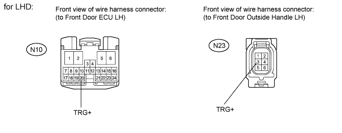
for LHD:
-
Disconnect the N23 handle connector.
-
Disconnect the N10 ECU connector.
-
Measure the resistance according to the value(s) in the table below.
Standard resistance Tester Connection Condition Specified Condition N23-3 (TRG+) - N10-20 (TRG+) Always Below 1 Ω N23-3 (TRG+) - Body ground Always 10 kΩ or higher
-
-
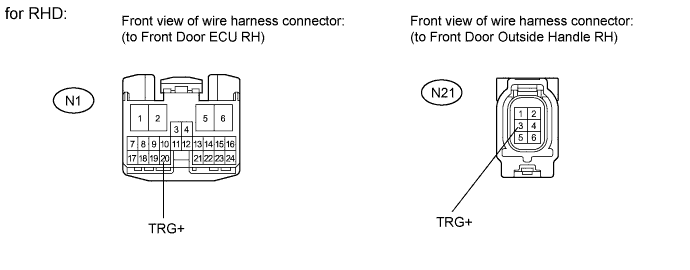
for RHD:
-
Disconnect the N21 handle connector.
-
Disconnect the N1 ECU connector.
-
Measure the resistance according to the value(s) in the table below.
Standard resistance Tester Connection Condition Specified Condition N21-3 (TRG+) - N1-20 (TRG+) Always Below 1 Ω N21-3 (TRG+) - Body ground Always 10 kΩ or higher
-
NG
REPAIR OR REPLACE HARNESS OR CONNECTOR
OK
-
-
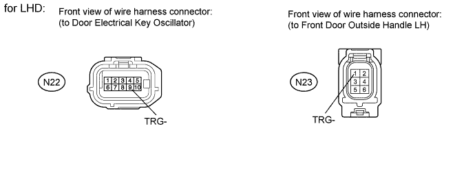
CHECK HARNESS AND CONNECTOR (FRONT DOOR OUTSIDE HANDLE - DOOR ELECTRICAL KEY OSCILLATOR)
-
for LHD:
-
Disconnect the N23 handle connector.
-
Disconnect the N22 oscillator connector.
-
Measure the resistance according to the value(s) in the table below.
Standard resistance Tester Connection Condition Specified Condition N23-1 (TRG-) - N22-9 (TRG-) Always Below 1 Ω N23-1 (TRG-) - Body ground Always 10 kΩ or higher

-
-
for RHD:
-
Disconnect the N21 handle connector.
-
Disconnect the N20 oscillator connector.
-
Measure the resistance according to the value(s) in the table below.
Standard resistance Tester Connection Condition Specified Condition N21-1 (TRG-) - N20-9 (TRG-) Always Below 1 Ω N21-1 (TRG-) - Body ground Always 10 kΩ or higher
-
NG
REPAIR OR REPLACE HARNESS OR CONNECTOR
OK
-
-
CHECK DOOR ELECTRICAL KEY OSCILLATOR (OPERATION)
-
Replace the door electrical key oscillator with a new one or normally functioning one Click here.
-
Check that the entry function operates normally.
OK Operates normally
NG
CHECK FRONT DOOR ECU (OPERATION) Click here
OK
END (DOOR ELECTRICAL OSCILLATOR IS DEFECTIVE)
-
-
CHECK FRONT DOOR ECU (OPERATION)
-
Replace the front door ECU LH*1 or RH*2 with a new one or normally functioning one Click here.
Tech Tips
*1: for LHD
*2: for RHD
-
Check that the entry function operates normally.
OK Operates normally
NG
REPLACE CERTIFICATION ECU
OK
END (FRONT DOOR ECU IS DEFECTIVE)
-