ENTRY AND START SYSTEM Front Passenger Side Door Entry Lock and Unlock Functions do not Operate
DESCRIPTION
When the front passenger door entry lock and unlock functions do not operate, one of the following may be malfunctioning: 1) power door lock system, 2) front passenger side door electrical key oscillator, or 3) certification ECU.
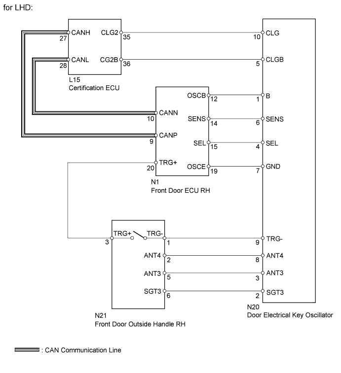
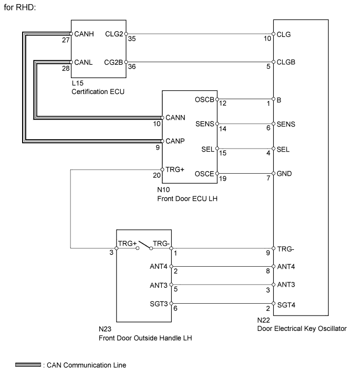
WIRING DIAGRAM
INSPECTION PROCEDURE
PROCEDURE
-
CHECK POWER DOOR LOCK OPERATION
-
When the master switch assembly's door control switch is operated, check that the locked doors unlock.
Result Result Proceed to Door locks operate normally OK Door locks do not operate normally NG
NG 
GO TO POWER DOOR LOCK CONTROL SYSTEM Click here
OK 
-
-
READ VALUE USING INTELLIGENT TESTER (DOOR LOCK POSITION SWITCH)
-
Using the intelligent tester, read the Data List.
Passenger Door (Front door ECU RH*1) (Front door ECU LH*2) Tester Display Measurement Item/Display Normal Condition Diagnostic Note Lock Position SW Front passenger side door lock position switch signal / ON or OFF ON: Front passenger side door is unlocked
OFF: Front passenger side door is locked
- Tech Tips
*1: for LHD
*2: for RHD
OK On intelligent tester screen, item changes between ON and OFF according to above chart.
NG
GO TO POWER DOOR LOCK CONTROL SYSTEM (Proceed to Only Passenger Door LOCK/UNLOCK Functions do not Operate) Click here
OK
-
-
READ VALUE USING INTELLIGENT TESTER (ENTRY SENSOR, OUTSIDE HANDLE TRIGGER SW)
-
Using the intelligent tester, read the Data List.
Passenger Door (Front door ECU LH*1) (Front door ECU RH*2) Tester Display Measurement Item/Display Normal Condition Diagnostic Note Entry Sensor Front passenger side door touch sensor / ON or OFF ON: Front passenger side door sensor is touched
OFF: Front passenger side door sensor is not touched
- Outside Handle Trigger SW Front passenger side door outside handle lock switch / ON or OFF ON: Front passenger side door outside handle lock switch is pushed
OFF: Front passenger side door outside handle lock switch is not pushed
- Tech Tips
*1: for LHD
*2: for RHD
Result Result Proceed to Display does not change according to manual operation A Display changes according to manual operation B
B 
CHECK WAVE ENVIRONMENT Click here
A
-
-
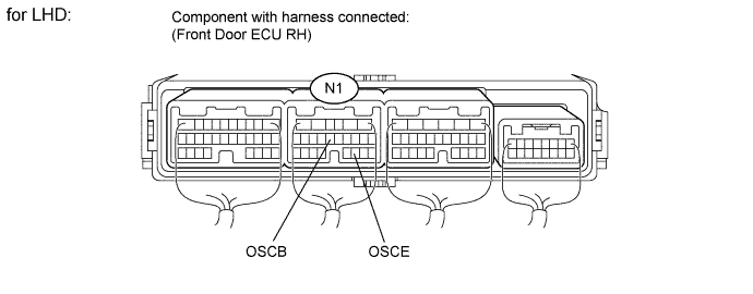
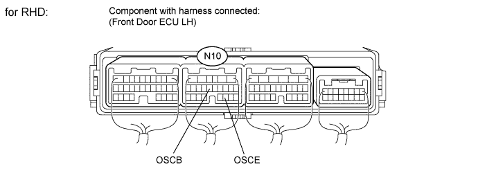
CHECK FRONT DOOR ECU
-
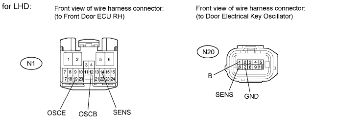
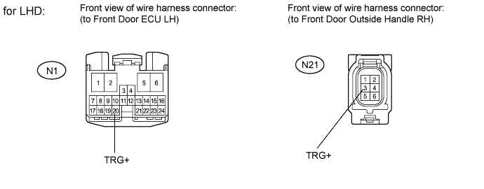
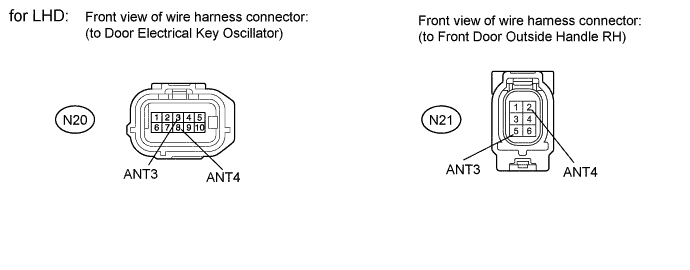
for LHD:
-
Measure the voltage according to the value(s) in the table below.
Standard voltage Tester Connection Condition Specified Condition N1-12 (OSCB) - N1-19 (OSCE) Always 11 to 14 V
-
-
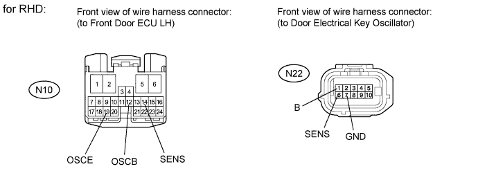
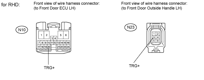
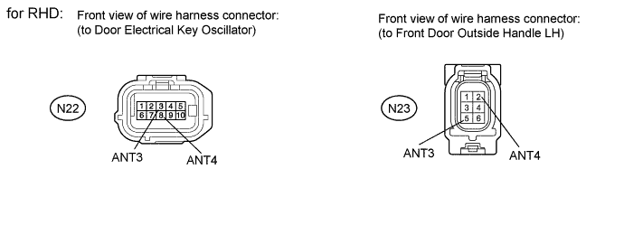
for RHD:
-
Measure the voltage according to the value(s) in the table below.
Standard voltage Tester Connection Condition Specified Condition N10-12 (OSCB) - N10-19 (OSCE) Always 11 to 14 V
-
NG
REPLACE FRONT DOOR ECU Click here
OK
-
-
CHECK HARNESS AND CONNECTOR (DOOR ELECTRICAL KEY OSCILLATOR - FRONT DOOR ECU)
-
for LHD:
-
Disconnect the N20 oscillator connector.
-
Disconnect the N1 ECU connector.
-
Measure the resistance according to the value(s) in the table below.
Standard resistance Tester Connection Condition Specified Condition N20-1 (B) - N1-12 (OSCB) Always Below 1 Ω N20-6 (SENS) - N1-14 (SENS) Always Below 1 Ω N20-7 (GND) - N1-19 (OSCE) Always Below 1 Ω N20-1 (B) - Body ground Always 10 kΩ or higher N20-6 (SENS) - Body ground Always 10 kΩ or higher N20-7 (GND) - Body ground Always 10 kΩ or higher
-
-
for RHD:
-
Disconnect the N22 oscillator connector.
-
Disconnect the N10 ECU connector.
-
Measure the resistance according to the value(s) in the table below.
Standard resistance Tester Connection Condition Specified Condition N22-1 (B) - N10-12 (OSCB) Always Below 1 Ω N22-6 (SENS) - N10-14 (SENS) Always Below 1 Ω N22-7 (GND) - N10-19 (OSCE) Always Below 1 Ω N22-1 (B) - Body ground Always 10 kΩ or higher N22-6 (SENS) - Body ground Always 10 kΩ or higher N22-7 (GND) - Body ground Always 10 kΩ or higher
-
NG
REPAIR OR REPLACE HARNESS OR CONNECTOR
OK
-
-
CHECK HARNESS AND CONNECTOR (DOOR ELECTRICAL KEY OSCILLATOR - FRONT DOOR OUTSIDE HANDLE)
-
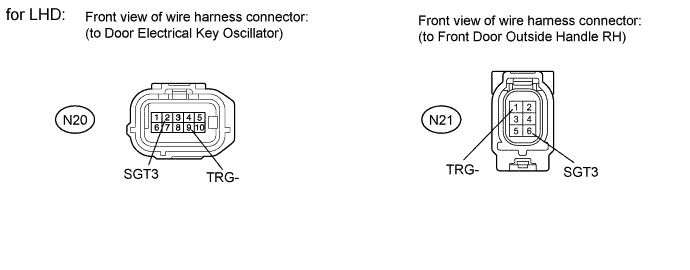
for LHD:
-
Disconnect the N20 oscillator connector.
-
Disconnect the N21 handle connector.
-
Measure the resistance according to the value(s) in the table below.
Standard resistance Tester Connection Condition Specified Condition N20-2 (SGT3) - N21-6 (SGT3) Always Below 1 Ω N20-9 (TRG-) - N21-1 (TRG-) Always Below 1 Ω N20-2 (SGT3) - Body ground Always 10 kΩ or higher N20-9 (TRG-) - Body ground Always 10 kΩ or higher
-
-
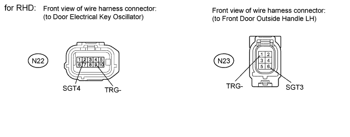
for RHD:
-
Disconnect the N22 oscillator connector.
-
Disconnect the N23 handle connector.
-
Measure the resistance according to the value(s) in the table below.
Standard resistance Tester Connection Condition Specified Condition N22-2 (SGT4) - N23-6 (SGT3) Always Below 1 Ω N22-9 (TRG-) - N23-1 (TRG-) Always Below 1 Ω N22-2 (SGT4) - Body ground Always 10 kΩ or higher N22-9 (TRG-) - Body ground Always 10 kΩ or higher
-
NG
REPAIR OR REPLACE HARNESS OR CONNECTOR
OK
-
-
CHECK HARNESS AND CONNECTOR (FRONT DOOR ECU - FRONT DOOR OUTSIDE HANDLE)
-
for LHD:
-
Disconnect the N21 handle connector.
-
Disconnect the N1 ECU connector.
-
Measure the resistance according to the value(s) in the table below.
Standard resistance Tester Connection Condition Specified Condition N21-3 (TRG+) - N1-20 (TRG+) Always Below 1 Ω N21-3 (TRG+) - Body ground Always 10 kΩ or higher
-
-
for RHD:
-
Disconnect the N23 handle connector.
-
Disconnect the N10 ECU connector.
-
Measure the resistance according to the value(s) in the table below.
Standard resistance Tester Connection Condition Specified Condition N23-3 (TRG+) - N10-20 (TRG+) Always Below 1 Ω N23-3 (TRG+) - Body ground Always 10 kΩ or higher
-
NG
REPAIR OR REPLACE HARNESS OR CONNECTOR
OK
-
-
CHECK DOOR ELECTRICAL KEY OSCILLATOR (OPERATION)
-
Replace the door electrical key oscillator with a new one or normally functioning one Click here.
-
Check that the entry function operates normally.
OK Operates normally
NG
CHECK FRONT DOOR OUTSIDE HANDLE (OPERATION) Click here
OK 
END (DOOR ELECTRICAL KEY OSCILLATOR IS DEFECTIVE)
-
-
CHECK FRONT DOOR OUTSIDE HANDLE (OPERATION)
-
Replace the front door outside handle RH*1 or LH*2 with a new one or normally functioning one Click here.
Tech Tips
*1: for LHD
*2: for RHD
-
Check that the entry function operates normally.
OK Operates normally
NG
REPLACE FRONT DOOR ECU Click here
OK
END (FRONT DOOR OUTSIDE HANDLE IS DEFECTIVE)
-
-
CHECK WAVE ENVIRONMENT
-
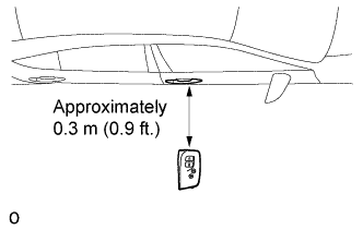
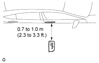
Bring the electrical key transmitter near the front passenger door outside handle, and perform a front passenger door entry lock and unlock operation check.
Note
If the key is brought within 0.2 m (0.6 ft.) of the door handle, communication is not possible.
Tech Tips
-
When the electrical key transmitter is brought near the front passenger door outside handle, the possibility of wave interference decreases, and it can be determined if wave interference is causing the problem symptom.
-
If the inspection result is that the operation check is normal, the possibility of wave interference is high. Also, added vehicle components may cause wave interference. If installed, remove them and perform the operation check.
-
On opposite side for RHD vehicle.
-
B
AFFECTED BY WAVE INTERFERENCE
A
-
-
KEY DIAGNOSTIC MODE
-
Diagnostic mode inspection (front passenger door outside oscillator)
Tech Tips
On opposite side for RHD vehicle.
-
Connect the intelligent tester to the DLC3.
-
Turn the engine switch on (IG).
-
Turn the intelligent tester on.
-
Enter the following menus:
-
Intelligent tester - Select: Body / Entry & Start / Key Communication Check / Overhead + Passenger Side /
-
-
When the electrical key transmitter is in the position shown in the illustration, check that the wireless door lock buzzer sounds.
Tech Tips
If the buzzer sounds, it can be determined that the front passenger seat outside transmitter is operating normally.
OK Wireless door lock buzzer sounds
-
NG
CHECK HARNESS AND CONNECTOR (DOOR ELECTRICAL KEY OSCILLATOR - CERTIFICATION ECU) Click here
OK
END (CERTIFICATION ECU IS DEFECTIVE)
-
-
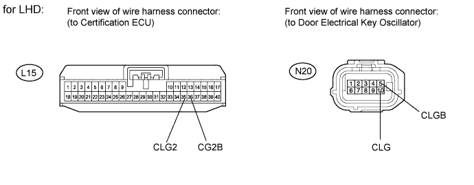
CHECK HARNESS AND CONNECTOR (DOOR ELECTRICAL KEY OSCILLATOR - CERTIFICATION ECU)
-
for LHD:
-
Disconnect the N20 oscillator connector.
-
Disconnect the L15 ECU connector.
-
Measure the resistance according to the value(s) in the table below.
Standard resistance Tester Connection Condition Specified Condition N20-5 (CLGB) - L15-36 (CG2B) Always Below 1 Ω N20-10 (CLG) - L15-35 (CLG2) Always Below 1 Ω N20-5 (CLGB) - Body ground Always 10 kΩ or higher N20-10 (CLG) - Body ground Always 10 kΩ or higher
-
-
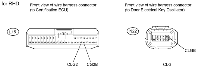
for RHD:
-
Disconnect the N22 oscillator connector.
-
Disconnect the L15 ECU connector.
-
Measure the resistance according to the value(s) in the table below.
Standard resistance Tester Connection Condition Specified Condition N22-5 (CLGB) - L15-36 (CG2B) Always Below 1 Ω N22-10 (CLG) - L15-35 (CLG2) Always Below 1 Ω N22-5 (CLGB) - Body ground Always 10 kΩ or higher N22-10 (CLG) - Body ground Always 10 kΩ or higher
-
NG
REPAIR OR REPLACE HARNESS OR CONNECTOR
OK
-
-
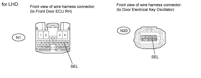
CHECK HARNESS AND CONNECTOR (DOOR ELECTRICAL KEY OSCILLATOR - FRONT DOOR ECU)
-
for LHD:
-
Disconnect the N20 oscillator connector.
-
Disconnect the N1 ECU connector.
-
Measure the resistance according to the value(s) in the table below.
Standard resistance Tester Connection Condition Specified Condition N20-4 (SEL) - N1-15 (SEL) Always Below 1 Ω N20-4 (SEL) - Body ground Always 10 kΩ or higher
-
-
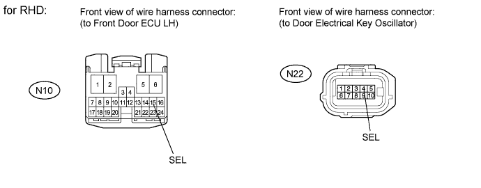
for RHD:
-
Disconnect the N22 oscillator connector.
-
Disconnect the N10 ECU connector.
-
Measure the resistance according to the value(s) in the table below.
Standard resistance Tester Connection Condition Specified Condition N22-4 (SEL) - N10-15 (SEL) Always Below 1 Ω N22-4 (SEL) - Body ground Always 10 kΩ or higher
-
NG
REPAIR OR REPLACE HARNESS OR CONNECTOR
OK
-
-
CHECK HARNESS AND CONNECTOR (DOOR ELECTRICAL KEY OSCILLATOR - FRONT DOOR OUTSIDE HANDLE)
-
for LHD:
-
Disconnect the N20 oscillator connector.
-
Disconnect the N21 handle connector.
-
Measure the resistance according to the value(s) in the table below.
Standard resistance Tester Connection Condition Specified Condition N20-3 (ANT3) - N21-5 (ANT3) Always Below 1 Ω N20-8 (ANT4) - N21-2 (ANT4) Always Below 1 Ω N20-3 (ANT3) - Body ground Always 10 kΩ or higher N20-8 (ANT4) - Body ground Always 10 kΩ or higher
-
-
for RHD:
-
Disconnect the N22 oscillator connector.
-
Disconnect the N23 handle connector.
-
Measure the resistance according to the value(s) in the table below.
Standard resistance Tester Connection Condition Specified Condition N22-3 (ANT3) - N23-5 (ANT3) Always Below 1 Ω N22-8 (ANT4) - N23-2 (ANT4) Always Below 1 Ω N22-3 (ANT2) - Body ground Always 10 kΩ or higher N22-8 (ANT4) - Body ground Always 10 kΩ or higher
-
NG
REPAIR OR REPLACE HARNESS OR CONNECTOR
OK
-
-
CHECK DOOR ELECTRICAL KEY OSCILLATOR (OPERATION)
-
Replace the door electrical key oscillator with a new one or normally functioning one Click here.
-
Check that the entry function operates normally.
OK Operates normally
NG
CHECK FRONT DOOR OUTSIDE HANDLE (OPERATION) Click here
OK
END (DOOR ELECTRICAL KEY OSCILLATOR IS DEFECTIVE)
-
-
CHECK FRONT DOOR OUTSIDE HANDLE (OPERATION)
-
Replace the front door outside handle RH*1 or LH*2 with a new one or normally functioning one Click here.
Tech Tips
*1: for LHD
*2: for RHD
-
Check that the entry function operates normally.
OK Operates normally
NG
CHECK FRONT DOOR ECU (OPERATION) Click here
OK
END (FRONT DOOR OUTSIDE HANDLE IS DEFECTIVE)
-
-
CHECK FRONT DOOR ECU (OPERATION)
-
Replace the front door ECU RH*1 or LH*2 with a new one or normally functioning one Click here.
Tech Tips
*1: for LHD
*2: for RHD
-
Check that the entry function operates normally.
OK Operates normally
NG
REPLACE CERTIFICATION ECU
OK
END (FRONT DOOR ECU IS DEFECTIVE)
-