ENTRY AND START SYSTEM All Door Entry Lock/Unlock Functions and Wireless Functions do not Operate
DESCRIPTION
When the entry operation and wireless operation door lock function does not operate, a malfunction or wave interference may be occurring in either of the following: 1) signal communication line between the door control receiver and certification ECU (line is used by entry and wireless); or 2) electrical key transmitter.
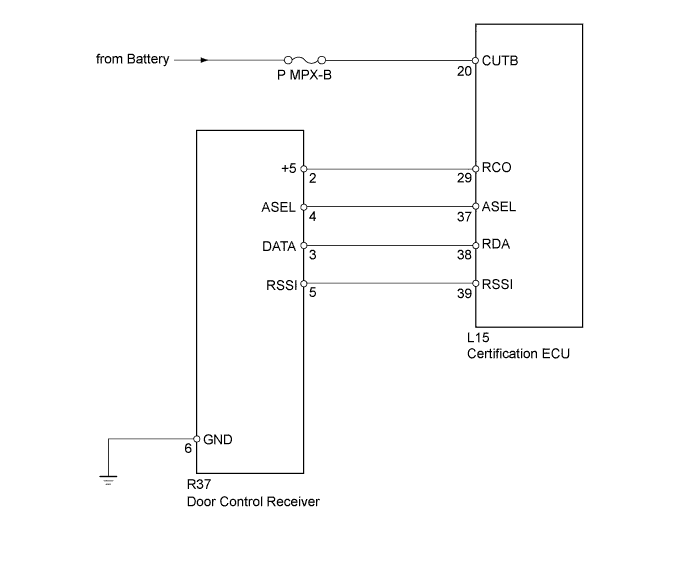
WIRING DIAGRAM
INSPECTION PROCEDURE
PROCEDURE
-
CHECK POWER DOOR LOCK SYSTEM
-
When the master switch assembly's door control switch is operated, check that the locked doors unlock.
Result Result Proceed to Door locks operate normally OK Door locks do not operate normally NG
NG 
GO TO POWER DOOR LOCK CONTROL SYSTEM Click here
OK 
-
-
CHECK ELECTRICAL KEY TRANSMITTER
-
When another registered electrical key transmitter is used, check that the entry function operates normally.
Result Result Proceed to Entry function operates normally A Entry function does not operate normally B
B 
CHECK WAVE ENVIRONMENT Click here
A
-
-
INSPECT TRANSMITTER BATTERY (VOLTAGE)
-
Remove the battery (lithium battery) from the transmitter Click here.
-
Inspect the battery capacity Click here.
NG
REPLACE TRANSMITTER BATTERY Click here
OK 
REPLACE ELECTRICAL KEY TRANSMITTER
-
-
CHECK WAVE ENVIRONMENT
-
Bring the electrical key transmitter near the door control receiver, and perform a wireless operation check.
Tech Tips
When the electrical key transmitter is brought near the door control receiver, the possibility of wave interference decreases, and it can be determined if wave interference is causing the problem symptom.
Result Result Proceed to Operation check fails A Operation check is normal B Tech Tips
If the inspection result is that the problem only occurs in certain locations or times of day, the possibility of wave interference is high. Also, added vehicle components may cause wave interference. If installed, remove them and perform the operation check.
B
AFFECTED BY WAVE INTERFERENCE
A
-
-
INSPECT FUSE (P MPX-B)
-
Remove the P MPX-B fuse from the passenger side junction block.
-
Measure the resistance according to the value(s) in the table below.
Standard resistance Tester Connection Condition Specified Condition P MPX-B fuse Always Below 1 Ω
NG
REPLACE FUSE
OK
-
-
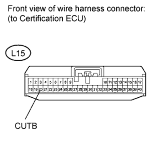
CHECK HARNESS AND CONNECTOR (CERTIFICATION ECU - BATTERY)
-
Disconnect the L15 ECU connector.
-
Measure the voltage according to the value(s) in the table below.
Standard voltage Tester Connection Condition Specified Condition L15-20 (CUTB) - Body ground Always 11 to 14 V
NG
REPAIR OR REPLACE HARNESS OR CONNECTOR
OK
-
-
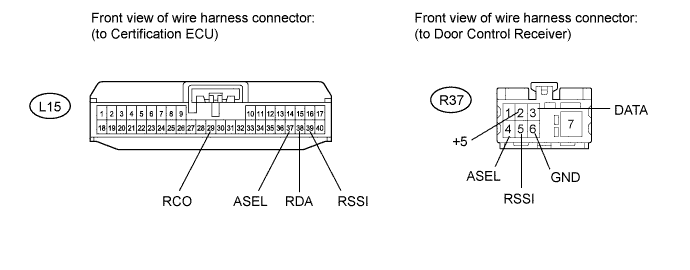
CHECK HARNESS AND CONNECTOR (DOOR CONTROL RECEIVER - CERTIFICATION ECU AND BODY GROUND)
-
Disconnect the R37 receiver connector.
-
Disconnect the L15 ECU connector.
-
Measure the resistance according to the value(s) in the table below.
Standard resistance Tester Connection Condition Specified Condition R37-2 (+5) - L15-29 (RCO) Always Below 1 Ω R37-3 (DATA) - L15-38 (RDA) Always Below 1 Ω R37-4 (ASEL) - L15-37 (ASEL) Always Below 1 Ω R37-5 (RSSI) - L15-39 (RSSI) Always Below 1 Ω R37-6 (GND) - Body ground Always Below 1 Ω R37-2 (+5) - Body ground Always 10 kΩ or higher R37-3 (DATA) - Body ground Always 10 kΩ or higher R37-4 (ASEL) - Body ground Always 10 kΩ or higher R37-5 (RSSI) - Body ground Always 10 kΩ or higher
NG
REPAIR OR REPLACE HARNESS OR CONNECTOR
OK
-
-
CHECK DOOR CONTROL RECEIVER (OPERATION)
-
Replace the door control receiver with a normal one Click here.
-
Check that it operates normally.
OK Operates normally
NG
REPLACE CERTIFICATION ECU
OK
END (DOOR CONTROL RECEIVER IS DEFECTIVE)
-