ENTRY AND START SYSTEM TERMINALS OF ECU

-
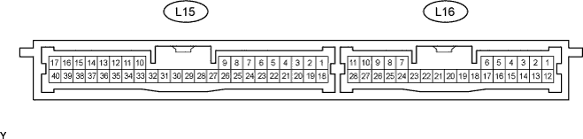
CHECK CERTIFICATION ECU
-
Disconnect the L15 ECU connector.
-
Measure the voltage and resistance according to the value(s) in the table below.
Terminal No. (Symbols) Wiring Color Terminal Description Condition Specified Condition L15-1 (+B1 ) - L15-17 (E) L - W-B +B power supply Always 11 to 14 V L15-18 (IG) - L15-17 (E) L - W-B Ignition power supply Engine switch off Below 1 V Engine switch on (IG) 11 to 14 V L15-20 (CUTB) - L15-17 (E) R - W-B +B power supply Always 11 to 14 V L15-17 (E) - Body ground W-B - Body ground Ground Always Below 1 Ω If the result is not as specified, the wire harness side may have a malfunction.
-
Reconnect the L15 ECU connector.
-
Measure the voltage according to the value(s) in the table below.
Terminal No. (Symbols) Wiring Color Terminal Description Condition Specified Condition L15-33 (CLG1) - L15-34 (CG1B) P - V*1
LG - L*2
Door electrical key oscillator (for front LH) sensor signal All doors closed, all doors locked and engine switch off Alternating between 5 V and below 1 V Door unlocked or door open Below 1 V L15-35 (CLG2) - L15-36 (CG2B) LG - L*1
P - V*2
Door electrical key oscillator (for front RH) sensor signal All doors closed, all doors locked and engine switch off Alternating between 5 V and below 1 V Door unlocked or door open Below 1 V L16-8 (CLG3) -L16-9 (CG3B) R - G*1
LG - L*2
Door electrical key oscillator (for rear LH) sensor signal All doors closed, all doors locked and engine switch off Alternating between 5 V and below 1 V Door unlocked or door open Below 1 V L16-10 (CLG4) - L16-11 (CG4B) LG - L*1
R - G*2
Door electrical key oscillator (for rear RH) sensor signal All doors closed, all doors locked and engine switch off Alternating between 5 V and below 1 V Door unlocked or door open Below 1 V L15-11 (CLG5) - L15-12 (CG5B) L - Y Indoor electrical key oscillator (for front) sensor signal 30 seconds after driver side door opened and closed, engine switch off Alternating between 5 V and below 1 V Within 30 seconds driver side door opened and closed, engine switch off Below 1 V L15-13 (CLG6) - L15-14 (CG6B) B - Y Indoor electrical key oscillator (for rear) sensor signal 30 seconds after driver side door opened and closed, engine switch off Alternating between 5 V and below 1 V Within 30 seconds driver side door opened and closed, engine switch off Below 1 V L15-15 (CLG7) - L15-16 (CG7B) W - B Indoor electrical key oscillator (for luggage room) sensor signal Luggage electrical key switch off Alternating between 5 V and below 1 V Luggage electrical key switch off Below 1 V L15-31 (CLG8) - L15-32 (CG8B) V - P Electrical key antenna (for luggage room) sensor signal Luggage electrical key switch off Alternating between 5 V and below 1 V Luggage electrical key switch on Below 1 V L15-29 (RCO) - L15-17 (E) G - W-B Door control receiver power source Engine switch off, all doors closed, and transmitter switch pressed 4.6 to 5.4 V Engine switch off, all doors closed, and transmitter switch not pressed Below 1 V L-15-37 (ASEL) - L15-17 (E) L - W-B Door control receiver select signal Engine switch off, all doors closed, and luggage compartment door closed Below 1 V Engine switch off, all doors closed, and luggage compartment door open 4.6 to 5.4 V L15-38 (RDA) - L15-17 (E) R - W-B Door control receiver data input signal Engine switch off, all doors closed, and transmitter switch not pressed Below 2 V Engine switch off, all doors closed, and transmitter switch pressed 11 to 14 V L-15-39 (RSSI) - L15-17 (E) W - W-B Door control receiver electric wave existence signal Engine switch off, all doors closed, and transmitter switch not pressed 11 to 14 V Engine switch off, all doors closed, and transmitter switch pressed Below 2 V Tech Tips
*1: for LHD
*2: for RHD
-
-
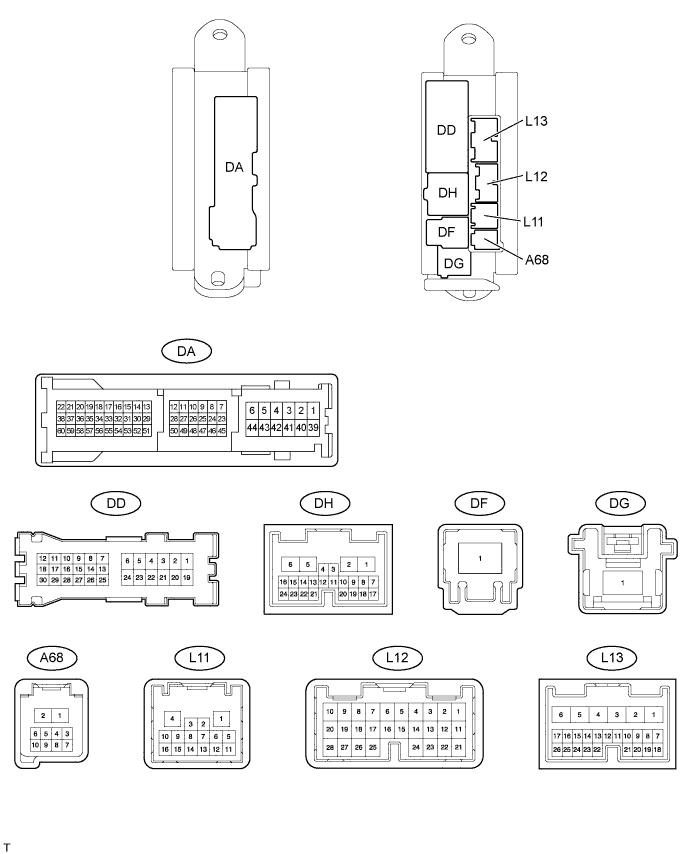
CHECK MAIN BODY ECU (DRIVER SIDE JUNCTION BLOCK)
-
Disconnect the DA, DD, DF, L11, L12, L13 and A68 ECU connectors.
-
Measure the voltage and resistance according to the value(s) in the table below.
Terminal No. (Symbols) Wiring Color Terminal Description Condition Specified Condition L11-1 (GND3) - DA-41 (GND1) W-B - W-B Ground Always Below 1 Ω DA-40 (GND1) - Body ground W-B - Body ground Ground Always Below 1 Ω DA-40 (GND2) - Body ground W-B - Body ground Ground Always Below 1 Ω DF-1 (ALTB) - Body ground B - Body ground IG power supply Always 11 to 14 V L12-1 (AM2) - Body ground W - Body ground Battery power supply Always 11 to 14 V L13-6 (AM1) - Body ground W - Body ground Battery power supply Always 11 to 14 V L13-24 (DCTY) - Body ground W - Body ground Driver side door courtesy light switch input Driver side door is open Below 1 Ω Driver side door is closed 10 kΩ or higher L12-21 (PCTY) - Body ground L - Body ground Passenger side door courtesy light switch input Passenger side door is open Below 1 Ω Passenger side door is closed 10 kΩ or higher L12-7 (RCTY) - Body ground R - Body ground Rear RH side door courtesy light switch input Rear RH side door is open Below 1 Ω Rear RH side door is closed 10 kΩ or higher DD-12 (LCTY) - Body ground L - Body ground Rear LH side door courtesy light switch input Rear LH side door is open Below 1 Ω Rear LH side door is closed 10 kΩ or higher
-
-
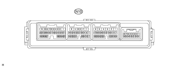
CHECK FRONT DOOR ECU LH
-
Disconnect the N10 ECU connector.
-
Measure the resistance and voltage according to the value(s) in the table below.
Terminal No. (Symbols) Wiring Color Terminal Description Condition Specified Condition N10-1 (GND) - Body ground W-B - Body ground Ground Always Below 1 Ω N10-6 (BDR) - N10-1 (GND) BE - W-B Battery power supply Always 11 to 14 V N10-11 (CPUB) - N10-1 (GND) B - W-B*1
R - W-B*2
Battery power supply Always 11 to 14 V Tech Tips
*1: for LHD
*2: for RHD
If the result is not as specified, the wire harness side may have a malfunction.
-
Reconnect the N10 ECU connector.
-
Measure the voltage according to the value(s) in the table below.
Terminal No. (Symbols) Wiring Color Terminal Description Condition Specified Condition N10-12 (OSCB) - N10-19 (OSCE) B - V Power source supply Always 11 to 14 V N10-14 (SENS) - N10-1 (GND) Y - W-B Touch sensor detection signal Outside door handle touched 11 to 14 V Outside door handle not touched Below 1 V N10-15 (SEL) - N10-1 (GND) BE - W-B Touch sensor activation control signal Key at least 3 m (9.8 ft.) away from door 11 to 14 V Key close to door Below 1 V N10-20 (TRG+) - N10-1 (GND) L - W-B Lock switch signal Engine switch off, all doors closed and lock switch not pushed Pulse generation (see waveform 1 or 2) Lock switch pushed Below 1 V -
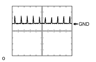
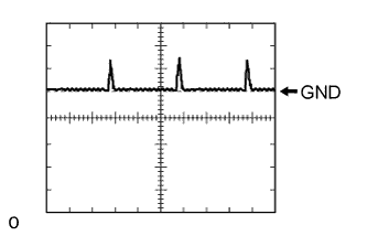
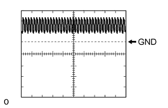
Using an oscilloscope, check the waveform 1.
Waveform 1 (Reference): Item Content Terminal No. (Symbols) N10-20 (TRG+) - N10-1 (GND) Tool Setting 5 V/DIV., 20 ms/DIV. Condition Engine switch off, all doors closed and lock switch not pushed -
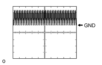
Using an oscilloscope, check the waveform 2.
Waveform 2 (Reference): Item Content Terminal No. (Symbols) N10-20 (TRG+) - N10-1 (GND) Tool Setting 5 V/DIV., 20 ms/DIV. Condition Engine switch off, all doors closed and lock switch not pushed
-
-
CHECK FRONT DOOR ECU RH
-
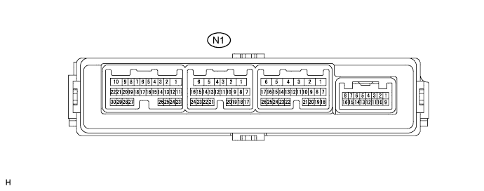
Disconnect the N1 ECU connector.
-
Measure the resistance and voltage according to the value(s) in the table below.
Terminal No. (Symbols) Wiring Color Terminal Description Condition Specified Condition N1-1 (GND) - Body ground W-B - Body ground Ground Always Below 1 Ω N1-6 (BDR) - N1-1 (GND) BE - W-B Battery power supply Always 11 to 14 V N1-11 (CPUB) - N1-1 (GND) R - W-B*1
B - W-B*2
Battery power supply Always 11 to 14 V Tech Tips
*1: for LHD
*2: for RHD
If the result is not as specified, the wire harness side may have a malfunction.
-
Reconnect the N1 ECU connector.
-
Measure the voltage according to the value(s) in the table below.
Terminal No. (Symbols) Wiring Color Terminal Description Condition Specified Condition N1-12 (OSCB) - N1-19 (OSCE) B - V Power source supply Always 11 to 14 V N1-14 (SENS) - N1-1 (GND) Y - W-B Touch sensor detection signal Outside door handle touched 11 to 14 V Outside door handle not touched Below 1 V N1-15 (SEL) - N1-1 (GND) BE - W-B Touch sensor activation control signal Key at least 3 m (9.8 ft.) away from door 11 to 14 V Key close to door Below 1 V N1-20 (TRG+) - N1-1 (GND) L - W-B Lock switch signal Engine switch off, all doors closed and lock switch not pushed Pulse generation (see waveform 1 or 2) Lock switch pushed Below 1 V -
Using an oscilloscope, check the waveform 1.
Waveform 1 (Reference): Item Content Terminal No. (Symbols) N1-20 (TRG+) - N1-1 (GND) Tool Setting 5 V/DIV., 20 ms/DIV. Condition Engine switch off, all doors closed and lock switch not pushed -
Using an oscilloscope, check the waveform 2.
Waveform 2 (Reference): Item Content Terminal No. (Symbols) N10-20 (TRG+) - N10-1 (GND) Tool Setting 5 V/DIV., 20 ms/DIV. Condition Engine switch off, all doors closed and lock switch not pushed
-
-
CHECK REAR DOOR ECU LH
-
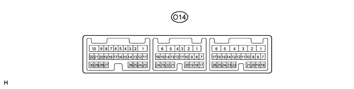
Disconnect the O14 ECU connector.
-
Measure the resistance and voltage according to the value(s) in the table below.
Terminal No. (Symbols) Wiring Color Terminal Description Condition Specified Condition O14-1 (GND) - Body ground W-B - Body ground Ground Always Below 1 Ω O14-6 (BDR) - O14-1 (GND) L - W-B Battery power supply Always 11 to 14 V O14-11 (CPUB) - O14-1 (GND) R - W-B Battery power supply Always 11 to 14 V If the result is not as specified, the wire harness side may have a malfunction.
-
Reconnect the O14 ECU connector.
-
Measure the voltage according to the value(s) in the table below.
Terminal No. (Symbols) Wiring Color Terminal Description Condition Specified Condition O14-12 (OSCB) - O14-15 (OSCE) B - V Power source supply Always 11 to 14 V O14-14 (SENS) - O14-1 (GND) Y - W-B Touch sensor detection signal Outside door handle touched 11 to 14 V Outside door handle not touched Below 1 V O14-16 (SEL) - O14-1 (GND) BE - W-B Touch sensor activation control signal Key at least 3 m (9.8 ft.) away from door 11 to 14 V Key close to door Below 1 V O14-20 (TRG+) - O14-1 (GND) L - W-B Lock switch signal Engine switch off, all doors closed and lock switch not pushed Pulse generation (see waveform 1 or 2) Lock switch pushed Below 1 V -
Using an oscilloscope, check the waveform 1.
Waveform 1 (Reference): Item Content Terminal No. (Symbols) O14-20 (TRG+) - O14-1 (GND) Tool Setting 5 V/DIV., 20 ms/DIV. Condition Engine switch off, all doors closed and lock switch not pushed -
Using an oscilloscope, check the waveform 2.
Waveform 2 (Reference): Item Content Terminal No. (Symbols) O14-20 (TRG+) - O14-1 (GND) Tool Setting 5 V/DIV., 20 ms/DIV. Condition Engine switch off, all doors closed and lock switch not pushed
-
-
CHECK REAR DOOR ECU RH

-
Disconnect the O3 ECU connector.
-
Measure the resistance and voltage according to the value(s) in the table below.
Terminal No. (Symbols) Wiring Color Terminal Description Condition Specified Condition O3-1 (GND) - Body ground W-B - Body ground Ground Always Below 1 Ω O3-6 (BDR) - O3-1 (GND) L - W-B Battery power supply Always 11 to 14 V O3-11 (CPUB) - O3-1 (GND) R - W-B Battery power supply Always 11 to 14 V If the result is not as specified, the wire harness side may have a malfunction.
-
Reconnect the O3 ECU connector.
-
Measure the voltage according to the value(s) in the table below.
Terminal No. (Symbols) Wiring Color Terminal Description Condition Specified Condition O3-12 (OSCB) - O3-15 (OSCE) B - V Power source supply Always 11 to 14 V O3-14 (SENS) - O3-1 (GND) Y - W-B Touch sensor detection signal Outside door handle touched 11 to 14 V Outside door handle not touched Below 1 V O3-16 (SEL) - O3-1 (GND) BE - W-B Touch sensor activation control signal Key at least 3 m (9.8 ft.) away from door 11 to 14 V Key close to door Below 1 V O3-20 (TRG+) - O3-1 (GND) L - W-B Lock switch signal Engine switch off, all doors closed and lock switch not pushed Pulse generation (see waveform 1 or 2) Lock switch pushed Below 1 V -
Using an oscilloscope, check the waveform 1.
Waveform 1 (Reference): Item Content Terminal No. (Symbols) O3-20 (TRG+) - O3-1 (GND) Tool Setting 5 V/DIV., 20 ms/DIV. Condition Engine switch off, all doors closed and lock switch not pushed -
Using an oscilloscope, check the waveform 2.
Waveform 2 (Reference): Item Content Terminal No. (Symbols) O3-20 (TRG+) - O3-1 (GND) Tool Setting 5 V/DIV., 20 ms/DIV. Condition Engine switch off, all doors closed and lock switch not pushed
-
-
CHECK POWER TRUNK LID ECU

-
Disconnect the S43 ECU connector.
-
Measure the voltage and resistance according to the value(s) in the table below.
Terminal No. (Symbols) Wiring Color Terminal Description Condition Specified Condition S43-11 (GND) - Body ground W-B - Body ground Ground Always Below 1 Ω S43-10 (ECUB) - Body ground B - Body ground Battery power supply Always 11 to 14 V S43-12 (B) - Body ground G - Body ground Battery power supply Always 11 to 14 V If the result is not as specified, the wire harness side may have a malfunction.
-
Reconnect the S43 ECU connector.
-
Measure the voltage according to the value(s) in the table below.
Terminal No. (Symbols) Wiring Color Terminal Description Condition Specified Condition S43-19 (LPSW) - S43-11 (GND) BR - W-B Luggage electrical key switch signal Engine switch on (IG) and Luggage electrical key switch pushed Below 1 V Engine switch on (IG), luggage compartment door closed and luggage electrical key switch not pushed Pulse generation (see waveform 1) S43-22 (LCTY) - S43-11 (GND) G - W-B Luggage compartment door courtesy light switch signal Engine switch on (IG) and Luggage compartment door is open Below 1 V Engine switch on (IG) and luggage compartment door is closed Pulse generation (see waveform 2) -
Using an oscilloscope, check the waveform 1.
Waveform 1 (Reference): Item Content Terminal No. (Symbols) S43-19 (LPSW) - S43-11 (GND) Tool Setting 5 V/DIV., 20 ms/DIV. Condition Engine switch on (IG), luggage compartment door closed and luggage electrical key switch not pushed -
Using an oscilloscope, check the waveform 2.
Waveform 2 (Reference): Item Content Terminal No. (Symbols) S43-22 (LCTY) - S43-11 (GND) Tool Setting 5 V/DIV., 20 ms/DIV. Condition Engine switch on (IG) and luggage compartment door is closed
-