ENTRY AND START SYSTEM Room Oscillator does not Recognize Key
DESCRIPTION
If the room oscillator does not recognize key, either of the following may be the cause: 1) communication between the indoor electrical key oscillator (for front) and electrical key transmitter cannot be performed; or 2) communication between the indoor electrical key oscillator (for rear) and electrical key transmitter cannot be performed.
WIRING DIAGRAM
INSPECTION PROCEDURE
PROCEDURE
-
CHECK POWER DOOR LOCK OPERATION
-
When the master switch assembly's door control switch is operated, check that the locked doors unlock.
Result Result Proceed to Door locks operate normally OK Door locks do not operate normally NG
NG 
GO TO POWER DOOR LOCK CONTROL SYSTEM Click here
OK 
-
-
READ VALUE USING INTELLIGENT TESTER (AUTO ENTRY CANCEL SW)
-
Using the intelligent tester, read the Data List.
Entry & Start (Certification ECU) Tester Display Measurement Item/Display Normal Condition Diagnostic Note Auto Entry Cancel SW Entry function cancel / ON or OFF Mode status is displayed - Result Result Proceed to Entry function is OFF A Entry function is ON B
B
PERFORM CANCELLATION OF ENTRY KEY CANCEL FUNCTION Click here
A
-
-
CHECK ENTRY AND START SYSTEM
-
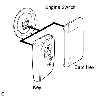
Remove the battery of the electrical key transmitter.
-
Touch the LEXUS mark of the key or card key to the engine switch.
-
Check that the engine switch can be turned on (IG).
Result Result Proceed to Engine switch can be turned on (IG) A Engine switch cannot be turned on (IG) (for 1UR-FSE) B Engine switch cannot be turned on (IG) (for 1UR-FE) C
B
GO TO ENTRY AND START SYSTEM (for 1UR-FSE) Click here
C
GO TO ENTRY AND START SYSTEM (for 1UR-FE) Click here
A
-
-
CHECK WAVE ENVIRONMENT
-
Install the battery to the electrical key transmitter.
-
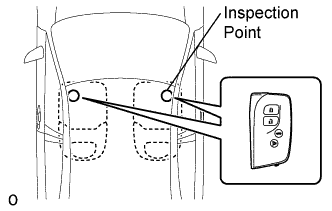
Bring the electrical key transmitter near the indoor electrical key oscillator (in center console), and perform an engine start check.
Note
If the key is brought within 0.2m (0.6 ft.) of the center console, communication is not possible.
-
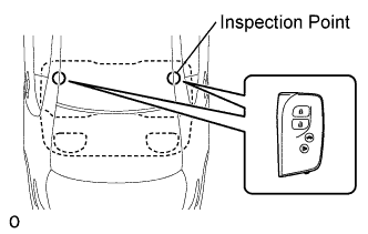
Bring the electrical key transmitter near the indoor electrical key oscillator (in rear seat cushion), and perform an engine start check.
Note
If the key is brought within 0.2m (0.6 ft.) of the rear seat cushion, communication is not possible.
Tech Tips
-
When the electrical key transmitter is brought near the indoor electrical key oscillator, the possibility of wave interference decreases, and it can be determined if wave interference is causing the problem symptom.
-
If the inspection result is that the operation check is normal, the possibility of wave interference is high. Also, added vehicle components may cause wave interference. If installed, remove them and perform the operation check.
Result Result Proceed to Both operation checks fail A Operation check is normal B -
B
AFFECTED BY WAVE INTERFERENCE
A
-
-
KEY DIAGNOSTIC MODE
-
Diagnostic mode inspection (front inside oscillator)
-
Connect the intelligent tester to the DLC3.
-
Turn the engine switch on (IG).
-
Turn the intelligent tester on.
-
Enter the following menus:
-
Intelligent tester - Select: Body / Entry & Start / Key Communication Check / Overhead + Front Room /
-
-
When the electrical key transmitter is placed on the driver seat or front passenger seat cushion, check that the wireless door lock buzzer sounds.
-
-
Diagnostic mode inspection (rear inside oscillator)
-
Connect the intelligent tester to the DLC3.
-
Turn the engine switch on (IG).
-
Turn the intelligent tester on.
-
Enter the following menus:
-
Intelligent tester - Select: Body / Entry & Start / Key Communication Check / Overhead + Rear Room /
-
-
When the electrical key transmitter is placed on the rear seat cushion, check that the wireless door lock buzzer sounds.
Tech Tips
If the buzzer sounds, it can be determined that the vehicle interior transmitters are operating normally.
Result Result Proceed to Front and rear operation check is normal A Front and rear operation checks fail B
-
A
REPLACE CERTIFICATION ECU
B
-
-
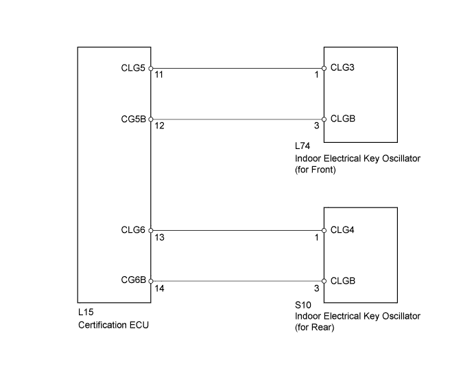
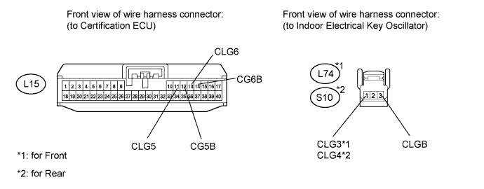
CHECK HARNESS AND CONNECTOR (INDOOR ELECTRICAL KEY OSCILLATOR - CERTIFICATION ECU)
-
Disconnect the L74 and S10 oscillator connectors.
-
Disconnect the L15 ECU connector.
-
Measure the resistance according to the value(s) in the table below.
Standard resistance for Front Tester Connection Condition Specified Condition L74-1 (CLG3) - L15-11 (CLG5) Always Below 1 Ω L74-3 (CLGB) - L15-12 (CG5B) Always Below 1 Ω L74-1 (CLG3) - Body ground Always 10 kΩ or higher L74-3 (CLGB) - Body ground Always 10 kΩ or higher Standard resistance for Rear Tester Connection Condition Specified Condition S10-1 (CLG4) - L15-13 (CLG6) Always Below 1 Ω S10-3 (CLGB) - L15-14 (CG6B) Always Below 1 Ω S10-1 (CLG4) - Body ground Always 10 kΩ or higher S10-3 (CLGB) - Body ground Always 10 kΩ or higher
NG
REPAIR OR REPLACE HARNESS OR CONNECTOR
OK
-
-
CHECK INDOOR ELECTRICAL KEY OSCILLATOR (OPERATION)
-
Replace the indoor electrical key oscillator with a new one or normally functioning one.
-
Check that the entry function operates normally.
OK Operates normally
NG 
REPLACE ELECTRICAL KEY TRANSMITTER Click here
OK 
END (INDOOR ELECTRICAL KEY OSCILLATOR IS DEFECTIVE)
-
-
REPLACE ELECTRICAL KEY TRANSMITTER
-
Replace the electrical key transmitter with a new one and perform the registration procedure.
NEXT
-
-
CHECK OPERATION
-
Check the operation of the entry lock function.
OK Operates normally
NG
REPLACE CERTIFICATION ECU
OK
END (KEY IS DEFECTIVE)
-