WIRELESS DOOR LOCK CONTROL SYSTEM Only Wireless Control Function is Inoperative
SYSTEM DESCRIPTION
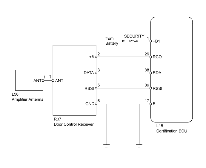
The door control receiver receives a signal from the transmitter via the amplifier antenna and send the signals to the main body ECU through the certification ECU via the CAN line. The main body ECU then controls all doors (including the luggage compartment door) by sending LOCK/UNLOCK signals to each door ECU and by sending a luggage compartment door open signal to the luggage closer motor assembly via the CAN line.
Note
-
Before performing the inspection, check that there are no problems related to the "CAN COMMUNICATION SYSTEM" and "LIN COMMUNICATION SYSTEM".
-
Check that DTC B1242 is not output.
-
If the door control transmitter or certification ECU is replaced, the codes must be registered.
-
Before performing the inspection, check that the following systems are operating normally.
-
Power door lock control system (lock/unlock function)
-
Power window control system (power window up/down function)
-
Sliding roof system (sliding roof open/close function)
-
Power trunk lid system (luggage compartment door open function)
-
Lighting system (door open/close function)
-
When troubleshooting a function, first make sure that the wireless door lock control functions are set to the default setting.
-
Before performing the inspection, use the "OPERATION CHECK" procedures to check that there are no problems with the basic wireless functions.
-
When replacing or inspecting the door control receiver and wire harness, do not change the position or length of the wire harness. If the wire harness is too close to the door control receiver, entry and wireless function performance may be affected.
WIRING DIAGRAM
INSPECTION PROCEDURE
PROCEDURE
-
CHECK DOOR CONTROL TRANSMITTER (LED)
-
Check that the transmitter's LED illuminates 3 times when the switch is pressed 3 times.
OK Transmitter's LED illuminates 3 times when switch is pressed 3 times.
OK 
CHECK DOOR CONTROL TRANSMITTER (OPERATION) Click here
NG 
-
-
REPLACE TRANSMITTER BATTERY
-
Temporarily replace the transmitter battery with a new one Click here.
-
Check that the doors can be locked and unlocked by using the transmitter LOCK/UNLOCK switch.
OK Doors can be locked and unlocked with transmitter.
NG
CHECK DOOR CONTROL TRANSMITTER (OPERATION) Click here
OK 
END (TRANSMITTER BATTERY IS DEFECTIVE)
-
-
CHECK DOOR CONTROL TRANSMITTER (OPERATION)
-
Temporarily replace the door control transmitter with a new one Click here.
-
Check that the doors can be locked and unlocked by using the transmitter LOCK/UNLOCK switch.
OK Doors can be locked and unlocked with transmitter.
NG
CHECK HARNESS AND CONNECTOR (CERTIFICATION ECU - DOOR CONTROL RECEIVER) Click here
OK
END (DOOR CONTROL TRANSMITTER IS DEFECTIVE)
-
-
CHECK HARNESS AND CONNECTOR (CERTIFICATION ECU - DOOR CONTROL RECEIVER)
-
Disconnect the L15 ECU connector.
-
Disconnect the R37 receiver connector.
-
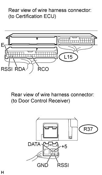
Measure the resistance according to the value(s) in the table below.
Standard resistance Tester Connection Condition Specified Condition L15-39 (RSSI) - R37-5 (RSSI) Always Below 1 Ω L15-38 (RDA) - R37-3 (DATA) L15-29 (RCO) - R37-2 (+5) L15-17 (E) - Body ground R37-6 (GND) - Body ground L15-39 (RSSI) or R37-5 (RSSI) - Body ground Always 10 kΩ or higher L15-38 (RDA) or R37-3 (DATA) - Body ground L15-29 (RCO) or R37-2 (+5) - Body ground
NG 
REPAIR OR REPLACE HARNESS OR CONNECTOR
OK
-
-
CHECK CERTIFICATION ECU
-
Disconnect the R37 receiver connector.
-
Measure the resistance and voltage according to the value(s) in the table below.
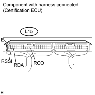
Standard resistance Tester Connection Condition Specified Condition L15-1 (E) - Body ground Always Below 1 Ω Standard voltage Tester Connection Condition Specified Condition L15-29 (RCO) - L15-1 (E) Always 4.5 to 5.4 V L15-39 (RSSI) - L15-1 (E) Engine switch off, all doors closed and transmitter switch not pressed 4.5 to 5.4 V Engine switch offF, all doors closed and transmitter switch pressed Below 1 V L15-38 (RDA) - L15-1 (E) Engine switch off, all doors closed and transmitter switch not pressed Below 1 V Engine switch off, all doors closed and transmitter switch pressed Pulse generation
NG
REPLACE CERTIFICATION ECU
OK
-
-
CHECK DOOR CONTROL RECEIVER (OUTPUT)
-
Measure the resistance and voltage according to the value(s) in the table below.
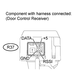
Standard resistance Tester Connection Condition Specified Condition R37-6 (GND) - Body ground Always Below 1 Ω Standard voltage Tester Connection Switch Condition Specified Condition R37-2 (+5) - R37-6 (GND) Engine switch off, all doors closed and transmitter switch pressed 4.5 to 5.4 V R37-5 (RSSI) - R37-6 (GND) Engine switch off, all doors closed and transmitter switch not pressed 11 to 14 V Engine switch off, all doors closed and transmitter switch pressed Below 1 V R37-3 (DATA) - R37-6 (GND) Engine switch off, all doors closed and transmitter switch not pressed Below 1 V Engine switch off, all doors closed and transmitter switch pressed Pulse generation
NG
REPLACE DOOR CONTROL RECEIVER Click here
OK
-
-
CHECK BACK WINDOW GLASS (WINDOW GLASS ANTENNA WIRE)
-
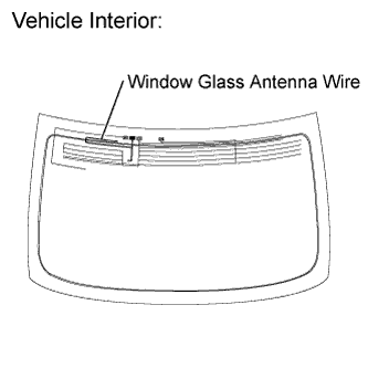
Visually inspect the entire window glass antenna wire's lines for breaks.
-
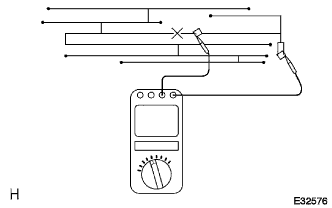
Using the tester, check that the window glass antenna wire's lines do not have continuity breaks.
Note
-
-
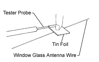
Wrap a piece of tin foil around the tip of the negative (-) tester probe as shown in the illustration. Press the foil against the wire's lines with your finger without damaging the wire, and inspect the wire.
-
If foreign matter on the glass needs to be cleaned, use a soft, dry cloth to wipe the glass along the wire's lines without damaging the wire.
-
Do not use standard detergents or glass cleaners.
-
Move the tin foil wrapped probe along the wire's lines, and check for line breaks.
OK Based on visual inspection and tester inspection, wire line breaks are not present.
-
NG
REPAIR WINDOW GLASS ANTENNA WIRE Click here
OK
-
-
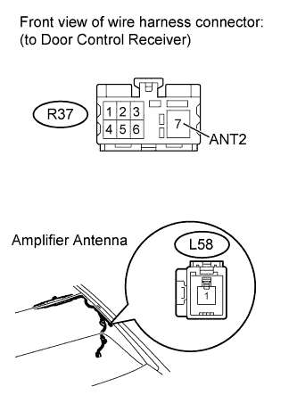
CHECK HARNESS AND CONNECTOR (DOOR CONTROL RECEIVER - AMPLIFIER ANTENNA)
-
Disconnect the R37 receiver connector.
-
Disconnect the U38 antenna connector.
-
Measure the resistance according to the value(s) in the table below.
Standard resistance Tester Connection Condition Specified Condition R37-7 (ANT) - U38-1 (ANT) Always Below 1 Ω R37-7 (ANT) or U38-1 (ANT) - Body ground Always 10 kΩ or higher
NG
REPAIR OR REPLACE HARNESS OR CONNECTOR
OK
-
-
CHECK AMPLIFIER ANTENNA ASSEMBLY (OPERATION)
-
Temporarily replace the amplifier antenna with a new one Click here.
-
Check that the doors can be locked and unlocked by using the transmitter LOCK/UNLOCK switch.
OK Doors can be locked and unlocked with transmitter.
NG
CHECK DOOR CONTROL RECEIVER (OPERATION) Click here
OK
END (AMPLIFIER ANTENNA IS DEFECTIVE)
-
-
CHECK DOOR CONTROL RECEIVER (OPERATION)
-
Temporarily replace the door control receiver with a new one Click here.
-
Check that the doors can be locked and unlocked by using the transmitter LOCK/UNLOCK switch.
OK Doors can be locked and unlocked with transmitter.
NG
CHECK CERTIFICATION ECU (OPERATION) Click here
OK
END (DOOR CONTROL RECEIVER IS DEFECTIVE)
-
-
CHECK CERTIFICATION ECU (OPERATION)
-
Temporarily replace the certification ECU with a new one.
-
Check that the doors can be locked and unlocked by using the transmitter LOCK/UNLOCK switch.
OK Doors can be locked and unlocked with transmitter.
NG
REPLACE MAIN BODY ECU (DRIVER SIDE JUNCTION BLOCK)
OK
END (CERTIFICATION ECU IS DEFECTIVE)
-