TURN SIGNAL FLASHER ASSEMBLY ON-VEHICLE INSPECTION

-
INSPECT TURN SIGNAL FLASHER ASSEMBLY
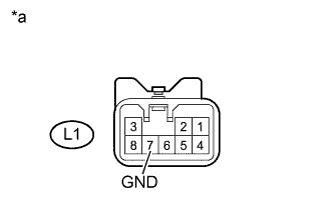
Text in Illustration *a Component with harness connected
(Turn Signal Flasher Assembly)
-
Measure the resistance according to the value(s) in the table below.
Standard Resistance Tester Connection Condition Specified Condition L1-7 (GND) - Body ground Always Below 1 Ω
-
If the result is not as specified, replace the turn signal flasher assembly.
-
-
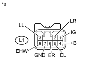
Text in Illustration *a Component with harness connected
(Turn Signal Flasher Assembly)
Measure the voltage according to the value(s) in the table below.
Standard Voltage Tester Connection Switch Condition Specified Condition L1-1 (IG) - L1-7 (GND) Engine switch on (IG) 11 to 14 V L1-2 (LR) - L1-7 (GND) Hazard warning switch OFF Below 1 V Hazard warning switch ON 9 V or higher (60 to 120 times per minute) L1-3 (LL) - L1-7 (GND) Hazard warning switch OFF Below 1 V Hazard warning switch ON 9 V or higher (60 to 120 times per minute) L1-4 (+B) - L1-7 (GND) Always 11 to 14 V L1-5 (EL) - L1-7 (GND) Headlight dimmer switch (TURN L) OFF 9 V or higher Headlight dimmer switch (TURN L) ON Below 1 V L1-6 (ER) - L1-7 (GND) Headlight dimmer switch (TURN R) OFF 9 V or higher Headlight dimmer switch (TURN R) ON Below 1 V L1-8 (EHW) - L1-7 (GND) Hazard warning switch OFF 9 V or higher Hazard warning switch ON Below 1 V If the result is not as specified, replace the turn signal flasher assembly.
-