INTERIOR ILLUMINATION LIGHT REMOVAL

Tech Tips
-
Use the same procedure for RHD and LHD vehicles.
-
The procedure listed below is for LHD vehicles.
-
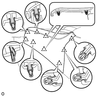
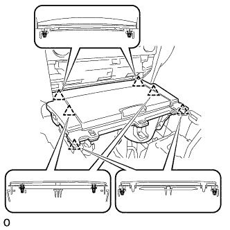
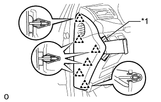
REMOVE INSTRUMENT PANEL FINISH PANEL END LH
-
Pull the front part of the instrument panel finish panel end LH to detach the 6 clips.
-
Pull the instrument panel finish panel end LH to detach 3 clips and remove the instrument panel finish panel end LH.
-
-
REMOVE INSTRUMENT PANEL FINISH PANEL END RH
Tech Tips
Use the same procedure described for the LH side.
-
REMOVE SHIFT LEVER KNOB SUB-ASSEMBLY
-
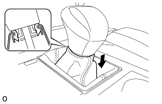
Lower the shift lever boot and disconnect it from the shift lever knob sub-assembly.
-
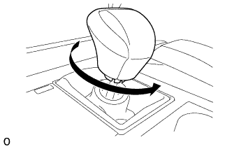
Twist the shift lever knob sub-assembly in the direction indicated by the arrow and remove it.
-
-
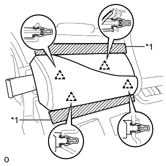
REMOVE UPPER INSTRUMENT CLUSTER FINISH PANEL
-
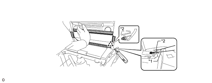
Apply protective tape as shown in the illustration.
-
Hold the opposite end with one hand as shown in the illustration so that the clip can be firmly pushed.
-
Insert a screwdriver at the location shown in the illustration, and then push the lower clip on the backside of the upper instrument cluster finish panel towards the rear of the vehicle to detach it.
Note
At this time, all the clips may become detached and the upper instrument cluster finish panel may suddenly come off. Therefore, slowly push on the clip to detach it.
Tech Tips
-
Tape the screwdriver tip before use.
-
The upper clip of the upper instrument cluster finish panel may become detached at the same time.
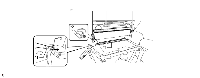
Text in Illustration *1 Protective Tape *2 Lower Clip 
Rear of the Vehicle - - -
-
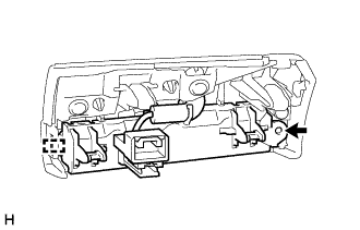
Insert a screwdriver at the location shown in the illustration, and then push the lower clip on the backside of the upper instrument cluster finish panel towards the rear of the vehicle to detach it.
Note
-
Slowly push on the clip to detach it.
-
At this time, all the clips may become detached and the upper instrument cluster finish panel may suddenly come off. Therefore, place one hand on the upper instrument cluster finish panel as shown in the illustration.
Tech Tips
-
Tape the screwdriver tip before use.
-
The upper clip of the upper instrument cluster finish panel may become detached at the same time.
Text in Illustration *1 Protective Tape *2 Lower Clip Rear of the Vehicle - - -
-
Text in Illustration *1 Protective Tape 
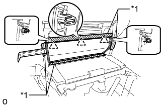
Upper Instrument Cluster Finish Panel Edge Insert moulding remover A between the upper instrument cluster finish panel and lower No. 1 instrument panel finish panel, and between the upper instrument cluster finish panel and lower No. 2 instrument panel finish panel to detach the 3 upper clips and remove the upper instrument cluster finish panel.
Note
If pressure is applied to the edge of the upper instrument cluster finish panel using moulding remover A, the surface may be damaged. Therefore, insert moulding remover A deep past the edge of the upper instrument cluster finish panel to detach the clips.
Tech Tips
If any of the upper clips have become detached during the previous procedure, detach the remaining clips to remove the upper instrument cluster finish panel.
-
-
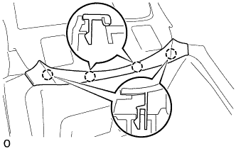
REMOVE NO. 3 BOX PANEL
-
Detach the 4 claws and remove the No. 3 box panel.
-
-
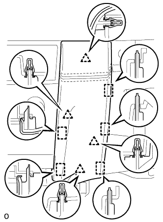
REMOVE UPPER REAR CONSOLE PANEL SUB-ASSEMBLY
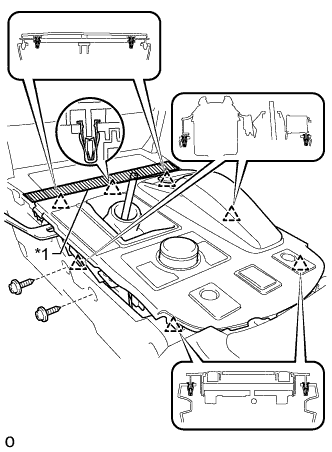
Text in Illustration *1 Protective Tape
-
Apply protective tape as shown in the illustration.
-
Move the shift lever to N.
-
Remove the 2 screws.
-
Detach the 6 clips and remove the upper rear console panel sub-assembly.
-
Disconnect each connector and each wire harness clamp.
-
-
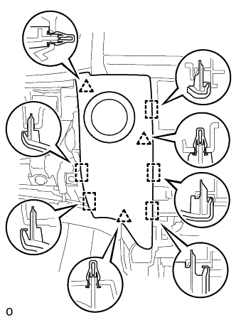
REMOVE UPPER CONSOLE PANEL SUB-ASSEMBLY
-
Disconnect the connector.
-
Detach the 6 clips and remove the upper console panel sub-assembly.
-
-
REMOVE LOWER NO. 1 INSTRUMENT PANEL FINISH PANEL
-
Detach the 4 clips and 5 guides and remove the lower No. 1 instrument panel finish panel.
-
Disconnect the connector.
-
-
REMOVE LOWER NO. 2 INSTRUMENT PANEL FINISH PANEL
-
Detach the 4 clips and 5 guides and remove the lower No. 2 instrument panel finish panel.
-
-
REMOVE MULTI-MEDIA MODULE RECEIVER ASSEMBLY
-
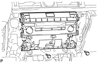
Remove the 2 bolts.
-
Detach the 6 clips and pull out the multi-media module receiver assembly with bracket.
-
Disconnect the connectors and remove the multi-media module receiver assembly with bracket.
-
-
REMOVE INSTRUMENT SIDE PANEL RH
Text in Illustration *1 Protective Tape
-
Apply protective tape as shown in the illustration.
-
Using moulding remover D, detach the 6 clips and remove the instrument side panel RH.
-
-
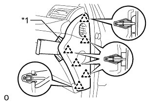
REMOVE INSTRUMENT CLUSTER FINISH PANEL GARNISH ASSEMBLY
-
Apply protective tape as shown in the illustration.
-
Using moulding remover B, detach the 12 clips and remove the instrument cluster finish panel garnish assembly.
-
Disconnect each connector.
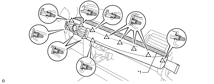
Text in Illustration *1 Protective Tape - -
-
-
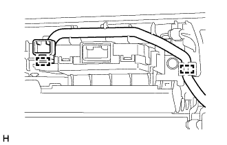
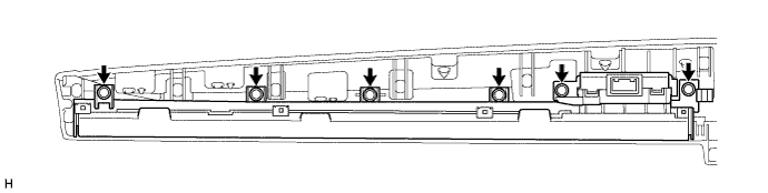
REMOVE NO. 1 INSTRUMENT PANEL GARNISH SUB-ASSEMBLY (INTERIOR ILLUMINATION LIGHT)
-
Detach the 2 clamps.
-
Remove the 6 screws and No. 1 instrument panel garnish sub-assembly (interior illumination light).
-
-
REMOVE INSTRUMENT SIDE PANEL LH
Text in Illustration *1 Protective Tape
-
Apply protective tape as shown in the illustration.
-
Using moulding remover D, detach the 6 clips and remove the instrument side panel LH.
-
-
REMOVE INSTRUMENT PANEL ORNAMENT
Text in Illustration *1 Protective Tape
-
Apply protective tape as shown in the illustration.
-
Using moulding remover B, detach the 4 clips and remove the instrument panel ornament.
-
Disconnect the connector.
-
-
REMOVE NO. 2 INSTRUMENT PANEL GARNISH SUB-ASSEMBLY (INTERIOR ILLUMINATION LIGHT)
-
Remove the screw.
-
Detach the guide to remove the No. 2 instrument panel garnish sub-assembly (interior illumination light).
-