HEADLIGHT ASSEMBLY (for LED Headlight) ADJUSTMENT

Tech Tips
-
Use the same procedure for the RH and LH sides.
-
The procedure listed below is for the LH side.
-
VEHICLE PREPARATION FOR HEADLIGHT AIMING ADJUSTMENT
-
Prepare the vehicle:
Tech Tips
-
Make sure that there is no damage to the body around the headlights.
-
Fill the fuel tank.
-
Make sure that the oil is filled to the specified level.
-
Make sure that the coolant is filled to the specified level.
-
Inflate the tires to the appropriate pressure.
-
Unload the trunk and vehicle, ensuring that the spare tire, tools and jack are in their original positions.
-
Have a person of average weight (75 kg, 165 lb) sit in the driver seat.
-
Bounce the vehicle at the corners up and down to stabilize the suspension.
-
Vehicles with an adjustable suspension should be set to the lowest vehicle height prior to adjusting the headlight aim.
-
-
-
PREPARATION FOR HEADLIGHT AIMING (Using a screen)
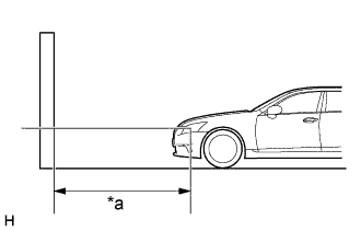
Text in Illustration *a 25 m or 3 m
-
except China:
Prepare the vehicle.
-
Place the vehicle in a location that is dark enough to clearly observe the cutoff line. The cutoff line is a distinct line, below which light from the headlights can be observed and above which it cannot.
-
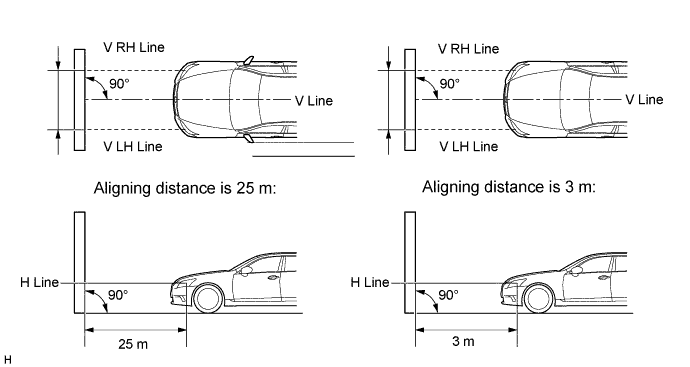
Place the vehicle at a 90° angle to the wall.
-
Create a 25 m (82 ft.) distance between the vehicle (headlight center) and the wall.
-
Make sure that the vehicle is on a level surface.
-
Bounce the vehicle up and down to settle the suspension.
Note
A distance of 25 m (82 ft.) between the vehicle (headlight center) and the wall is necessary for proper aim adjustment. If unavailable, secure a distance of exactly 3 m (9.84 ft.) for the check and adjustment. (The target zone will change with the distance, so follow the instructions in the illustration.)
-
-
Text in Illustration *a 10 m or 3 m for China:
Prepare the vehicle.
-
Place the vehicle in a location that is dark enough to clearly observe the cutoff line. The cutoff line is a distinct line, below which light from the headlights can be observed and above which it cannot.
-
Place the vehicle at a 90° angle to the wall.
-
Create a 10 m (32.8 ft) distance between the vehicle (headlight center) and the wall.
-
Make sure that the vehicle is on a level surface.
-
Bounce the vehicle up and down to settle the suspension.
Note
A distance of 10 m (32.8 ft.) between the vehicle (headlight center) and the wall is necessary for proper aim adjustment. If unavailable, secure a distance of exactly 3 m (9.84 ft.) for the check and adjustment. (The target zone will change with the distance, so follow the instructions in the illustration.)
-
-
Prepare a piece of thick white paper approximately 2 m (6.56 ft.) (height) x 4 m (13.1 ft.) (width) to use as a screen.
-
Draw a vertical line down the center of the screen (V line).
-
except China:
Set the screen as shown in the illustration.
Tech Tips
-
Stand the screen perpendicular to the ground.
-
Align the V line on the screen with the center of the vehicle.
-
-
for China:
Set the screen as shown in the illustration.
Tech Tips
-
Stand the screen perpendicular to the ground.
-
Align the V line on the screen with the center of the vehicle.

-
-
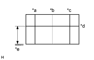
Text in Illustration *a V LH Line *b V Line *c V RH Line *d H Line *e Ground Draw base lines (H, V LH, and V RH lines) on the screen as shown in the illustration.
Tech Tips
-
The base lines differ for "low beam inspection" and "high beam inspection".
-
Mark the headlight center marks on the screen. If the center mark cannot be observed on the headlight, use the center of the headlight or the name of the manufacturer marked on the headlight as the center mark.
-
H Line (Headlight height):
Draw a horizontal line across the screen so that it passes through the center marks. The H line should be at the same height as the headlight center marks of the low beam headlights.
-
V LH Line and V RH Line (Center mark position of the left-hand (LH) and right-hand (RH) headlights):
Draw 2 vertical lines so that they intersect the H line at each center mark (aligned with the center of the low beam headlights).
-
-
-
INSPECT HEADLIGHT AIMING
-
Cover the headlight or disconnect the connector of the headlight/headlight ECU on the opposite side to prevent light from the headlight that is not being inspected from affecting the headlight aiming inspection.
Note
Do not keep the headlight covered for more than 3 minutes. The headlight lens is made of synthetic resin, which may melt or be damaged due to excessive heat.
Tech Tips
When checking the aim of the high beam headlight, cover the low beam headlight or disconnect the connector.
-
Start the engine.
-
except China:
Turn on the headlight and check if the cutoff line matches the preferred cutoff line in the following illustration.
Tech Tips
-
Since the low beam light and the high beam light on each side have separate reflectors, it is necessary to check and adjust the aim separately for both.
-
The illustration is for LHD vehicles. RHD vehicles are the opposite of the illustration.
-
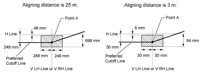
If the alignment distance is 25 m (82 ft.):
The low beam cutoff line should be within 48 mm (1.18 in.) and 698 mm (2.28 in.) below the H line as well as 249 mm (9.80 in.) left or right of the V LH or V RH line.
-
If the alignment distance is 3 m (9.84 ft.):
The low beam cutoff line should be within 6 mm (0.236 in.) and 84 mm (3.30 in.) below the H line as well as 30 mm (1.18 in.) left or right of the V LH or V RH line.
-
If the alignment distance is 25 m (82 ft.):
The horizontal line of the preferred low beam cutoff line is 249 mm (9.80 in.) below the H line and point A of the preferred low beam cutoff line is on the V LH or V RH line.
-
If the alignment distance is 3 m (9.84 ft.):
The horizontal line of the preferred low beam cutoff line is 30 mm (1.18 in.) below the H line and point A of the preferred low beam cutoff line is on the V LH or V RH line.
-
-
for China:
Turn on the headlight and check if the cutoff line matches the preferred cutoff line in the following illustration.
Tech Tips
-
Since the low beam light and the high beam light on each side have separate reflectors, it is necessary to check and adjust the aim separately for both.
-
If the alignment distance is 10 m (32.8 ft.):
The low beam cutoff line should be within 94 mm (3.70 in.) and 285 mm (11.2 in.) below the H line as well as 99 mm (3.89 in.) left or right of the V LH or V RH line.
-
If the alignment distance is 3 m (9.84 ft.):
The low beam cutoff line should be within 28 mm (1.10 in.) and 85 mm (3.34 in.) below the H line as well as 30 mm (1.18 in.) left or right of the V LH or V RH line.
-
If the alignment distance is 10 m (32.8 ft.):
The horizontal line of the preferred low beam cutoff line is 189 mm (7.44 in.) below the H line and point A of the preferred low beam cutoff line is on the V LH or V RH line.
-
If the alignment distance is 3 m (9.84 ft.):
The horizontal line of the preferred low beam cutoff line is 57 mm (2.24 in.) below the H line and point A of the preferred low beam cutoff line is on the V LH or V RH line.

-
-
except China:
Turn on the high beams and check if the center of intensity for each high beam matches the center of intensity in the illustration.
Tech Tips
-
Since the low beam light and the high beam light on each side have separate reflectors, it is necessary to check and adjust the aim separately for both.
-
If the alignment distance is 25 m (82.0 ft.):
The high beam center of intensity should be within 175 mm (6.88 in.) above and 249 mm (9.80 in.) below the H line as well as 497 mm (1.63 ft.) left or right of the V LH or V RH line.
-
If the alignment distance is 3 m (9.84 ft.):
The high beam center of intensity should be within 21 mm (0.827 in.) above and 30 mm (1.18 in.) below the H line as well as 60 mm (2.36 in.) left or right of the V LH or V RH line.

-
-
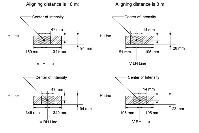
for China:
Turn on the high beams and check if the center of intensity for each high beam matches the center of intensity in the illustration.
Tech Tips
-
Since the low beam light and the high beam light on each side have separate reflectors, it is necessary to check and adjust the aim separately for both.
-
If the alignment distance is 10 m (32.8 ft.):
The high beam center of intensity should be within 47 mm (1.85 in.) below the H line.
-
If the alignment distance is 3 m (9.84 ft.):
The high beam center of intensity should be within 14 mm (0.55 in.) below the H line.
-
If the alignment distance is 10 m (32.8 ft.):
The high beam center of intensity for the headlight assembly LH should be within 169 mm (6.65 in.) left and 349 mm (1.14 ft.) right of the V LH line.
-
If the alignment distance is 3 m (9.84 ft.):
The high beam center of intensity for the headlight assembly LH should be within 51 mm (2.0 in.) left and 105 mm (4.13 in.) right of the V LH line.
-
If the alignment distance is 10 m (32.8 ft.):
The high beam center of intensity for the headlight assembly RH should be within 349 mm (1.14 ft.) left or right of the V RH line.
-
If the alignment distance is 3 m (9.84 ft.):
The high beam center of intensity for the headlight assembly RH should be within 105 mm (4.13 in.) left or right of the V RH line.
-
-
-
ADJUSTMENT HEADLIGHT AIMING
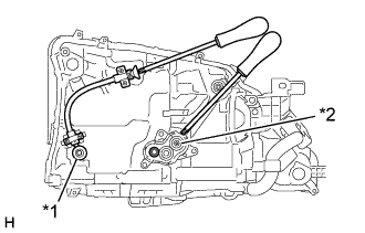
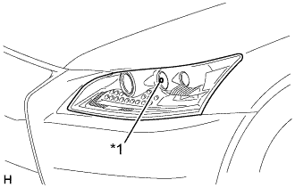
Text in Illustration *1 Vertical and Horizontal Aiming Screw *2 Vertical Aiming Screw
-
Headlight low beam.
-
Using a screwdriver, adjust the aim.
Adjust the aim of each headlight so that it is within the specified range by turning each aiming screw with a screwdriver.
Note
The final turn of the aiming screw should be made in the clockwise direction. If the screw is tightened excessively, loosen it and then retighten it, so that the final turn of the screw is in the clockwise direction.
Tech Tips
-
Since the low beam light and the high beam light on each side have separate reflectors, it is necessary to check and adjust the aim separately for both.
-
When adjusting the horizontal axis of the headlight, the vertical axis will also change. It is necessary to adjust the horizontal position first, and then correct the vertical position.
-
If it is not possible to correctly adjust headlight aim, headlight unit and headlight unit reflector installation.
-
The headlight aim moves up when turning the vertical aiming screw clockwise, and moves down when turning the vertical aiming screw counterclockwise. The headlight aim moves right when turning the horizontal aiming screw clockwise, and moves left when turning the horizontal aiming screw counterclockwise.
-
Confirm the direction of rotation of the aiming screw by observing it while it is being adjusted. Due to the position of the screwdriver, the direction of rotation of the adjusting screw can be different than the direction of rotation of the screwdriver being used to adjust it.
-
-
-
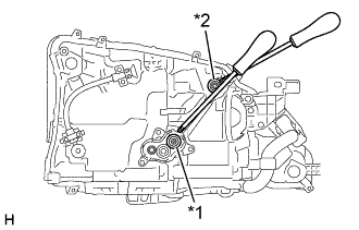
Text in Illustration *1 Vertical Aiming Screw *2 Vertical and Horizontal Aiming Screw Headlight high beam.
-
Using a screwdriver, adjust the aim.
Adjust the aim of each headlight so that it is within the specified range by turning each aiming screw with a screwdriver.
Note
The final turn of the aiming screw should be made in the clockwise direction. If the screw is tightened excessively, loosen it and then retighten it, so that the final turn of the screw is in the clockwise direction.
Tech Tips
-
Since the low beam light and the high beam light on each side have separate reflectors, it is necessary to check and adjust the aim separately for both.
-
When adjusting the horizontal axis of the headlight, the vertical axis will also change. It is necessary to adjust the horizontal position first, and then correct the vertical position.
-
If it is not possible to correctly adjust headlight aim, headlight unit and headlight unit reflector installation.
-
The headlight aim moves up when turning the vertical aiming screw clockwise, and moves down when turning the vertical aiming screw counterclockwise. The headlight aim moves right when turning the horizontal aiming screw clockwise, and moves left when turning the horizontal aiming screw counterclockwise.
-
Confirm the direction of rotation of the aiming screw by observing it while it is being adjusted. Due to the position of the screwdriver, the direction of rotation of the adjusting screw can be different than the direction of rotation of the screwdriver being used to adjust it.
-
-
-
-
ADJUST CUTOFF BEAM (w/ Adaptive High Beam System)
Tech Tips
-
Only perform this procedure when it is necessary to adjust the cutoff beam.
-
If the headlight beam axis has been adjusted, adjusting the cutoff beam is not necessary.
-
Preparation for adjustment:
-
Move the vehicle to a level surface.
-
Adjust the tire pressures to the specified pressure.
-
Fill the fuel tank.
-
Make sure the spare tire and standard tools are in their proper.
-
Sit a person of average weight (75 kg, 165 lb) in the driver's seat.
-
Bounce the vehicle at the corners up and down to stabilize the suspension.
-
Set the vehicle height at the lowest setting (for vehicles with an air suspension).
-
-
Adjust cut off beam:
-
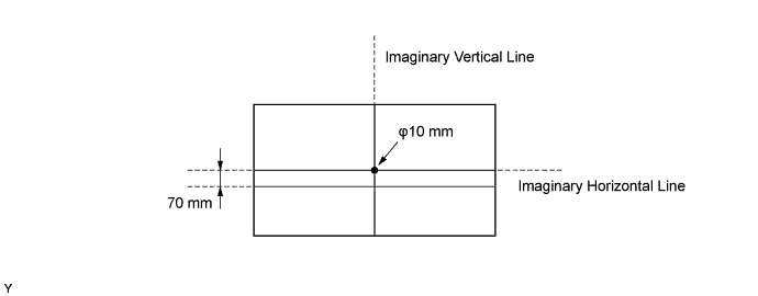
Prepare a screen as shown in the illustration.
-
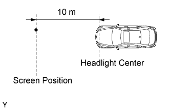
Have the screen face the front of the vehicle at a position 10 m away from the vehicle.
-
Text in Illustration *1 Low Beam Center Align the center of the imaginary lines on the screen with the center of the headlight.
-
Make sure that there is no light influence from other lights.
Note
-
Do not keep the headlight covered for more than 3 minutes.
-
The headlight lens is made of synthetic resin, which may melt or be damaged due to excessive heat.
-
-
Turn the power switch off and connect the GTS to the DLC3.
-
Turn the power switch on (READY).
-
Illuminate the headlights in low beam.
-
Enter the following menus: Body Electrical / AHS / Active Test / Cutoff Range Adaptive Beam LH or RH.
-
Select ON of the control range.
-
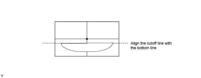
Adjust the cutoff beam in the vertical direction so that it is aligned with the bottom side of the screen.
Note
Use the low beam aiming screw to perform adjustments by turning it in the tightening direction (if the screw is loosened, make sure to tighten it again after loosening it).
-
Finish the Active Test.
-
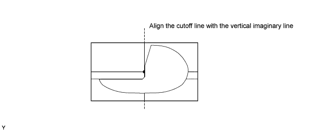
Enter the following menus: AHS / Utility / Shade Angle Adjustment.
-
Select the adjustment options according to the instructions on the screen and adjust the cutoff beam in the horizontal direction.
-
-