LIGHTING SYSTEM Back-up Light does not Illuminate
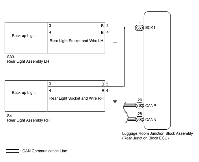
WIRING DIAGRAM
INSPECTION PROCEDURE
Note
First perform the communication function inspections in HOW TO PROCEED WITH TROUBLESHOOTING to confirm that there are no CAN communication malfunctions before troubleshooting this symptom.
PROCEDURE
-
PERFORM ACTIVE TEST USING GTS (BACK-UP LIGHT)
-
Using the GTS, perform the Active Test Click here.
Body No. 4 Tester Display Test Part Control Range Backup Light Back-up light operation OFF - ON OK Back-up light condition is switched by Active Test.
NG 
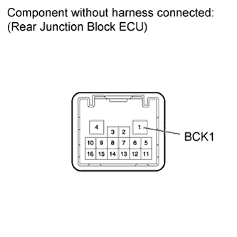
CHECK REAR JUNCTION BLOCK ECU (BCK1 VOLTAGE) Click here
OK 
GO TO AUTOMATIC TRANSMISSION SYSTEM Click here
-
-
CHECK REAR JUNCTION BLOCK ECU (BCK1 VOLTAGE)
-
Disconnect the S63 ECU connector.
Measure the voltage according to the value(s) in the table below.
Standard Voltage Tester Connection Switch Condition Specified Condition 1 (BCK1) - Body ground Engine switch on (IG), shift lever in R position 11 to 14 V Note
Do not start the engine.
NG 
REPLACE LUGGAGE ROOM JUNCTION BLOCK (REAR JUNCTION BLOCK ECU)
OK 
-
-
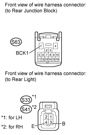
CHECK HARNESS AND CONNECTOR (REAR JUNCTION BLOCK ECU - REAR LIGHT AND BODY GROUND)
-
Disconnect the S63 rear junction block ECU connector.
-
Disconnect the S33*1 or S41*2 rear light connector.
-
*1: for LH
-
*2: for RH
-
-
Measure the resistance according to the value(s) in the table below.
Standard Resistance for LH Tester Connection Condition Specified Condition S63-1 (BCK1) - S33-3 (B) Always Below 1 Ω S33-4 (E) - Body ground Always Below 1 Ω S63-1 (BCK1) - Body ground Always 10 kΩ or higher for RH Tester Connection Condition Specified Condition S63-1 (BCK1) - S41-3 (B) Always Below 1 Ω S41-4 (E) - Body ground Always Below 1 Ω S63-1 (BCK1) - Body ground Always 10 kΩ or higher
NG
REPAIR OR REPLACE HARNESS OR CONNECTOR
OK
-
-
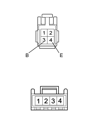
INSPECT REAR LIGHT SOCKET AND WIRE
-
Remove the rear light socket and wire Click here.
-
Measure the resistance according to the value(s) in the table below.
Standard Resistance Tester Connection Condition Specified Condition 3 (B) - 3 Always Below 1 Ω 4 (E) - 4 Always Below 1 Ω 3 (B) - 4 (E) Always 10 kΩ or higher
NG
REPLACE REAR LIGHT SOCKET AND WIRE Click here
OK
REPLACE REAR LIGHT ASSEMBLY Click here
-