LIGHTING SYSTEM Turn Signal Light does not Illuminate
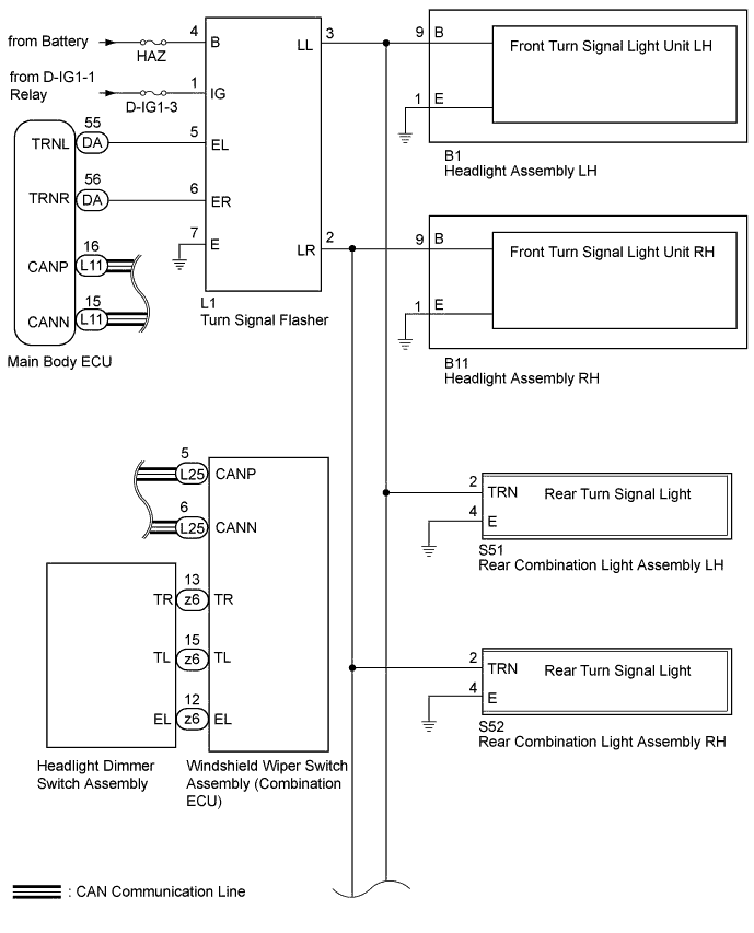
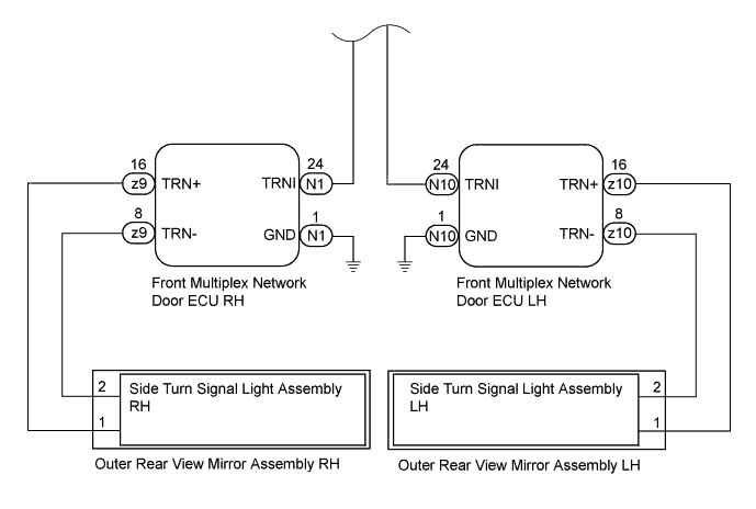
WIRING DIAGRAM
INSPECTION PROCEDURE
Note
-
First perform the communication function inspections in HOW TO PROCEED WITH TROUBLESHOOTING to confirm that there are no CAN communication malfunctions before troubleshooting this symptom.
-
Inspect the fuses for circuits related to this system before performing the following inspection procedure.
PROCEDURE
-
PERFORM ACTIVE TEST USING GTS (TURN SIGNAL LIGHT)
-
Using the GTS, perform the Active Test Click here.
Main Body Tester Display Test Part Control Range Turn Light RH Relay Operation Turn signal light operation OFF - ON Turn Light LH Relay Operation Turn signal light operation OFF - ON OK Turn signal light condition is switched by Active Test.
NG 
CONFIRM LIGHT POSITION Click here
OK 
-
-
READ VALUE USING GTS (HEADLIGHT DIMMER SWITCH)
-
Using the GTS, read the Data List Click here.
Combination Switch Tester Display Measurement Item/Display Normal Condition Diagnostic Note Turn Right Switch Headlight dimmer switch signal (Turn R position)/ON or OFF ON: Turn signal switch Turn R position
OFF: Turn signal switch OFF
- Turn Left Switch Headlight dimmer switch signal (Turn L position)/ON or OFF ON: Turn signal switch Turn L position
OFF: Turn signal switch OFF
- OK Condition sign can be displayed.
NG
INSPECT HEADLIGHT DIMMER SWITCH ASSEMBLY Click here
OK
-
-
CHECK WINDSHIELD WIPER SWITCH ASSEMBLY
-
Temporarily replace the windshield wiper switch with a new or normally functioning one Click here.
-
Check the turn signal light operation.
OK Turn signal light operation is normal.
NG 
REPLACE MAIN BODY ECU (DRIVER SIDE JUNCTION BLOCK ASSEMBLY)
OK 
END (WINDSHIELD WIPER SWITCH WAS DEFECTIVE)
-
-
INSPECT HEADLIGHT DIMMER SWITCH ASSEMBLY
-
Remove the headlight dimmer switch Click here.
-
Inspect the headlight dimmer switch Click here.
NG
REPLACE HEADLIGHT DIMMER SWITCH ASSEMBLY Click here
OK
REPLACE WINDSHIELD WIPER SWITCH ASSEMBLY Click here
-
-
CONFIRM LIGHT POSITION
-
Check the malfunctioning turn signal light.
Result Result Proceed to All lights do not illuminate A Lights on one side do not illuminate B
B
CHECK HARNESS AND CONNECTOR (HEADLIGHT - TURN SIGNAL FLASHER) Click here
A
-
-
CHECK HARNESS AND CONNECTOR (TURN SIGNAL FLASHER - BATTERY AND BODY GROUND)
-
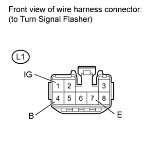
Disconnect the L1 turn signal flasher connector.
-
Measure the voltage according to the value(s) in the table below.
Standard Voltage Tester Connection Condition Specified Condition L1-4 (B) - Body ground Always 11 to 14 V L1-1 (IG) - Body ground Engine switch on (IG) 11 to 14 V -
Measure the resistance according to the value(s) in the table below.
Standard Resistance Tester Connection Condition Specified Condition L1-7 (E) - Body ground Always Below 1 Ω
NG
REPAIR OR REPLACE HARNESS OR CONNECTOR
OK
-
-
CHECK HARNESS AND CONNECTOR (MAIN BODY ECU - TURN SIGNAL FLASHER)
-
Disconnect the DA main body ECU connector.
-
Disconnect the L1 turn signal flasher connector.
-
Measure the resistance according to the value(s) in the table below.
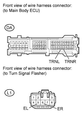
Standard Resistance Tester Connection Condition Specified Condition DA-55 (TRNL) - L1-5 (EL) Always Below 1 Ω DA-56 (TRNR) - L1-6 (ER) Always Below 1 Ω DA-55 (TRNL) - Body ground Always 10 kΩ or higher DA-56 (TRNR) - Body ground Always 10 kΩ or higher
NG
REPAIR OR REPLACE HARNESS OR CONNECTOR
OK
-
-
CHECK TURN SIGNAL FLASHER
-
Temporarily replace the turn signal flasher with a new or normally functioning one Click here.
-
Check the turn signal light operation.
OK Turn signal light operation is normal.
NG
REPLACE MAIN BODY ECU (DRIVER SIDE JUNCTION BLOCK ASSEMBLY)
OK
END (TURN SIGNAL FLASHER WAS DEFECTIVE)
-
-
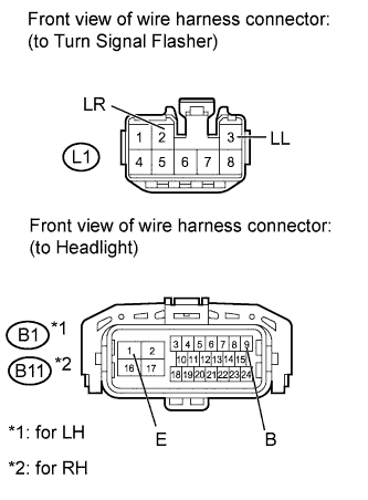
CHECK HARNESS AND CONNECTOR (HEADLIGHT - TURN SIGNAL FLASHER)
-
*1: for LH
-
*2: for RH
-
Disconnect the L1 turn signal flasher connector.
-
Disconnect the B1*1 or B11*2 headlight connector.
-
Disconnect the S51*1 or S52*2 rear combination light connector.
-
Disconnect the z10*1 or z9*2 outer rear view mirror connector.
-
Measure the resistance according to the value(s) in the table below.
Standard Resistance for LH Tester Connection Condition Specified Condition L1-3 (LL) - B1-9 Always Below 1 Ω L1-3 (LL) - Body ground Always 10 kΩ or higher for RH Tester Connection Condition Specified Condition L1-2 (LR) - B11-9 Always Below 1 Ω L1-2 (LR) - Body ground Always 10 kΩ or higher
NG
REPAIR OR REPLACE HARNESS OR CONNECTOR
OK
-
-
CHECK HARNESS AND CONNECTOR (MAIN BODY ECU - TURN SIGNAL FLASHER)
-
Disconnect the DA main body ECU connector.
-
Disconnect the L1 turn signal flasher connector.
-
Measure the resistance according to the value(s) in the table below.
Standard Resistance Tester Connection Condition Specified Condition DA-55 (TRNL) - L1-5 (EL) Always Below 1 Ω DA-56 (TRNR) - L1-6 (ER) Always Below 1 Ω DA-55 (TRNL) - Body ground Always 10 kΩ or higher DA-56 (TRNR) - Body ground Always 10 kΩ or higher
NG
REPAIR OR REPLACE HARNESS OR CONNECTOR
OK
-
-
CHECK TURN SIGNAL FLASHER
-
Temporarily replace the turn signal flasher with a new or normally functioning one Click here.
-
Check the turn signal light operation.
OK Turn signal light operation is normal.
NG
REPLACE MAIN BODY ECU (DRIVER SIDE JUNCTION BLOCK ASSEMBLY)
OK
END (TURN SIGNAL FLASHER WAS DEFECTIVE)
-