LIGHTING SYSTEM Room Light Control does not Operate
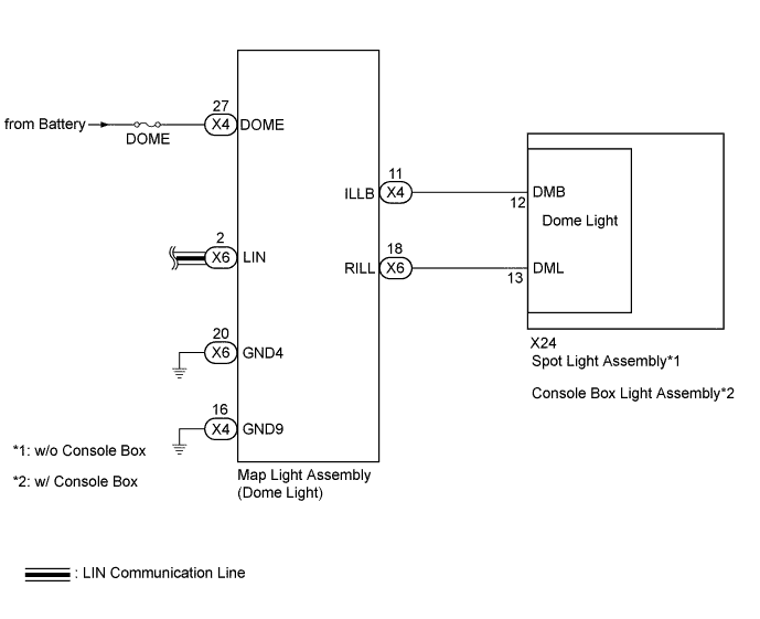
WIRING DIAGRAM
INSPECTION PROCEDURE
Note
-
First perform the communication function inspections in HOW TO PROCEED WITH TROUBLESHOOTING to confirm that there are no LIN communication malfunctions before troubleshooting this symptom.
-
Inspect the fuses for circuits related to this system before performing the following inspection procedure.
PROCEDURE
-
CHECK CONDITION
-
Check the malfunction conditions.
Result Result Proceed to All conditions below A Engine switch on (ACC) or (IG) → Engine switch off B All doors open → a door opened C All doors locked → a door unlocked D
B 
REPLACE MAIN BODY ECU (DRIVER SIDE JUNCTION BLOCK ASSEMBLY)
C
GO TO PROBLEM SYMPTOMS TABLE (COURTESY LIGHT) Click here
D
GO TO PROBLEM SYMPTOMS TABLE (DOOR UNLOCK) Click here
A 
-
-
CONFIRM LIGHT POSITION
-
Check the malfunctioning dome light.
Result Result Proceed to Front dome light and rear dome light A Front dome light B Rear dome light C
B
REPLACE MAP LIGHT ASSEMBLY Click here
C 
CHECK MAP LIGHT ASSEMBLY (ILLB VOLTAGE) Click here
A
-
-
CHECK HARNESS AND CONNECTOR (MAP LIGHT - BODY GROUND)
-
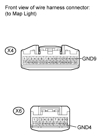
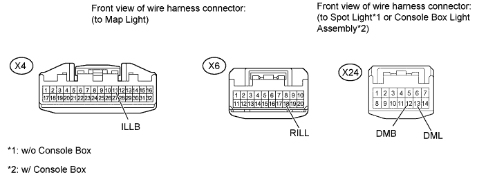
Disconnect the X4 and X6 map light connectors.
-
Measure the resistance according to the value(s) in the table below.
Standard Resistance Tester Connection Condition Specified Condition X4-16 (GND9) - Body ground Always Below 1 Ω X6-20 (GND4) - Body ground Always Below 1 Ω
NG
REPAIR OR REPLACE HARNESS OR CONNECTOR
OK
-
-
CHECK HARNESS AND CONNECTOR (BATTERY - MAP LIGHT)
-
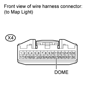
Disconnect the X4 map light connector.
-
Measure the voltage according to the value(s) in the table below.
Standard Voltage Tester Connection Condition Specified Condition X4-27 (DOME) - Body ground Always 11 to 14 V
NG
REPAIR OR REPLACE HARNESS OR CONNECTOR
OK 
REPLACE MAP LIGHT ASSEMBLY Click here
-
-
CHECK MAP LIGHT ASSEMBLY (ILLB VOLTAGE)
-
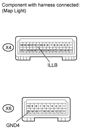
Remove the map light with its connector still connected.
-
Measure the voltage according to the value(s) in the table below.
Standard Voltage Tester Connection Condition Specified Condition X4-11 (ILLB) - X6-20 (GND4) Always 11 to 14 V
NG
REPLACE MAP LIGHT ASSEMBLY Click here
OK
-
-
CHECK HARNESS AND CONNECTOR (MAP LIGHT - SPOT LIGHT OR CONSOLE BOX LIGHT)
-
Disconnect the X4 and X6 map light connectors.
-
Disconnect the X24 spot light*1 or console box light assembly*2 connector.
-
*1: w/o Console Box
-
*2: w/ Console Box
-
-
Measure the resistance according to the value(s) in the table below.
Standard Resistance Tester Connection Condition Specified Condition X4-11 (ILLB) - X24-12 (DMB) Always Below 1 Ω X6-18 (RILL) - X24-13 (DML) Always Below 1 Ω X4-11 (ILLB) - Body ground Always 10 kΩ or higher X6-18 (RILL) - Body ground Always 10 kΩ or higher Result Result Proceed to OK (w/o Console Box) A OK (w/ Console Box) B NG C
B
CHECK CONSOLE BOX LIGHT ASSEMBLY Click here
C
REPAIR OR REPLACE HARNESS OR CONNECTOR
A
-
-
CHECK SPOT LIGHT ASSEMBLY
-
Temporarily replace the spot light with a new or normally functioning one Click here.
-
Check the spot light operation.
OK Spot light operation is normal.
NG
REPLACE MAP LIGHT ASSEMBLY Click here
OK
END (SPOT LIGHT WAS DEFECTIVE)
-
-
CHECK CONSOLE BOX LIGHT ASSEMBLY
-
Temporarily replace the console box light assembly with a new or normally functioning one Click here.
-
Check the console box light assembly operation.
OK console box light assembly operation is normal.
NG
REPLACE MAP LIGHT ASSEMBLY Click here
OK
END (CONSOLE BOX LIGHT WAS DEFECTIVE)
-