LIGHTING SYSTEM LO-beam Headlight does not Illuminate
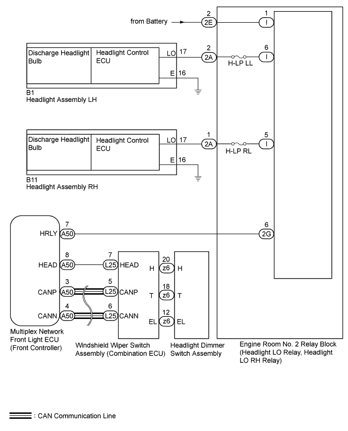
WIRING DIAGRAM
INSPECTION PROCEDURE
Note
-
First perform the communication function inspections in HOW TO PROCEED WITH TROUBLESHOOTING to confirm that there are no CAN communication malfunctions before troubleshooting this symptom.
-
Inspect the fuses for circuits related to this system before performing the following inspection procedure.
Tech Tips
If a discharge headlight bulb's condition cannot be determined through a visual check, replace with a normally functioning bulb or interchange the left and right bulbs and check its condition.
PROCEDURE
-
PERFORM ACTIVE TEST USING GTS (HEADLIGHT LOW)
-
Using the GTS, perform the Active Test Click here.
Body No. 5 Tester Display Test Part Control Range Head Light Low Low beam headlight illumination operation OFF - ON OK Condition sign can be displayed.
NG 
CHECK MULTIPLEX NETWORK FRONT LIGHT ECU (HRLY VOLTAGE) Click here
OK 
-
-
READ VALUE USING GTS (HEADLIGHT DIMMER SWITCH)
-
Using the GTS, read the Data List Click here.
Combination Switch Tester Display Measurement Item/Display Normal Condition Diagnostic Note Head Light Switch Headlight dimmer switch signal (HEAD position)/ON or OFF ON: Headlight dimmer switch HEAD position
OFF: Headlight dimmer switch OFF
- OK Condition sign can be displayed.
NG
INSPECT HEADLIGHT DIMMER SWITCH ASSEMBLY Click here
OK
-
-
CHECK HARNESS AND CONNECTOR (MULTIPLEX NETWORK FRONT LIGHT ECU - WINDSHIELD WIPER SWITCH)
-
Disconnect the A50 multiplex network front light ECU connector.
-
Disconnect the L25 windshield wiper switch connector.
-
Measure the resistance according to the value(s) in the table below.
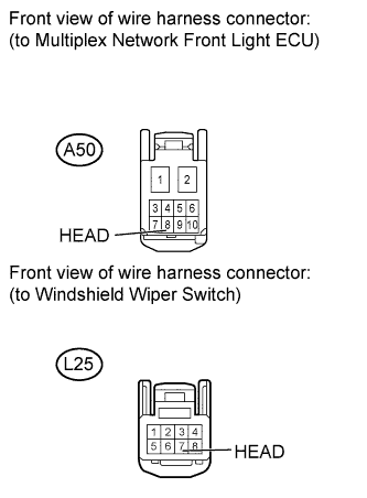
Standard Resistance Tester Connection Condition Specified Condition A50-8 (HEAD) - L25-7 (HEAD) Always Below 1 Ω
NG 
REPAIR OR REPLACE HARNESS OR CONNECTOR
OK
-
-
CHECK WINDSHIELD WIPER SWITCH (OPERATION)
-
Temporarily replace the windshield wiper switch with a new or normally functioning one Click here.
-
Check that the low beam headlight illuminates.
OK Low beam headlight illuminates.
NG
REPLACE MULTIPLEX NETWORK FRONT LIGHT ECU
OK 
END (WINDSHIELD WIPER SWITCH WAS DEFECTIVE)
-
-
INSPECT HEADLIGHT DIMMER SWITCH ASSEMBLY
-
Remove the headlight dimmer switch Click here.
-
Inspect the headlight dimmer switch Click here.
NG
REPLACE HEADLIGHT DIMMER SWITCH ASSEMBLY Click here
OK
REPLACE WINDSHIELD WIPER SWITCH Click here
-
-
CHECK MULTIPLEX NETWORK FRONT LIGHT ECU (HRLY VOLTAGE)
-
Disconnect the A50 multiplex network front light ECU connector.
-
Measure the voltage according to the value(s) in the table below.
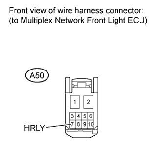
Standard Voltage Tester Connection Condition Specified Condition A50-7 (HRLY) - Body ground Always 11 to 14 V
NG
CHECK HARNESS AND CONNECTOR (MULTIPLEX NETWORK FRONT LIGHT ECU - ENGINE ROOM NO. 2 RELAY BLOCK) Click here
OK
REPLACE MULTIPLEX NETWORK FRONT LIGHT ECU
-
-
CHECK HARNESS AND CONNECTOR (MULTIPLEX NETWORK FRONT LIGHT ECU - ENGINE ROOM NO. 2 RELAY BLOCK)
-
Disconnect the A50 multiplex network front light ECU connector.
-
Disconnect the 2G engine room NO. 2 relay block connector.
-
Measure the resistance according to the value(s) in the table below.
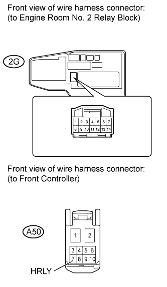
Standard Resistance Tester Connection Condition Specified Condition A50-7 (HRLY) - 2G-6 Always Below 1 Ω A50-7 (HRLY) - Body ground Always 10 kΩ or higher
NG
REPAIR OR REPLACE HARNESS OR CONNECTOR
OK
-
-
CHECK ENGINE ROOM NO. 2 RELAY BLOCK
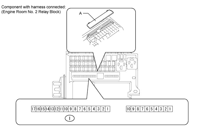
-
Remove the cover labeled A.
-
Measure the voltage according to the value(s) in the table below.
Standard Voltage Tester Connection Condition Specified Condition I-1 - Body ground Always 11 to 14 V
NG
INSPECT ENGINE ROOM NO. 2 RELAY BLOCK Click here
OK
REPLACE ENGINE ROOM NO. 2 RELAY BLOCK
-
-
INSPECT ENGINE ROOM NO. 2 RELAY BLOCK
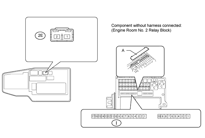
-
Remove the cover labeled A.
-
Disconnect the 2E engine room No. 2 relay block connector.
-
Measure the resistance according to the value(s) in the table below.
Standard Resistance Tester Connection Condition Specified Condition 2E-2 - I-1 Always Below 1 Ω
NG
REPLACE ENGINE ROOM NO. 2 RELAY BLOCK
OK
REPAIR OR REPLACE HARNESS OR CONNECTOR (BATTERY - ENGINE ROOM NO. 2 RELAY BLOCK)
-