LIGHTING SYSTEM Interior Foot Light does not Illuminate
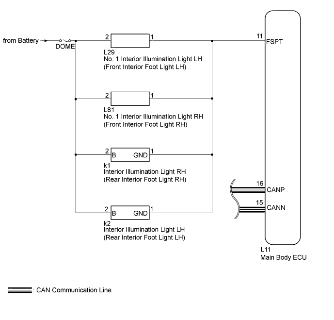
WIRING DIAGRAM
INSPECTION PROCEDURE
Note
-
First perform the communication function inspections in HOW TO PROCEED WITH TROUBLESHOOTING to confirm that there are no CAN communication malfunctions before troubleshooting this symptom.
-
Inspect the fuses for circuits related to this system before performing the following inspection procedure.
PROCEDURE
-
PERFORM ACTIVE TEST USING GTS (FRONT AND REAR INTERIOR FOOT LIGHT)
-
Using the GTS, perform the Active Test Click here.
Main Body Tester Display Test Part Control Range Fr Foot Light Front and rear interior foot light illumination operation OFF - ON OK Front and rear interior foot light condition can be switched by Active Test.
NG 
CHECK HARNESS AND CONNECTOR (FRONT INTERIOR FOOT LIGHT LH - BATTERY) Click here
OK 
REPLACE MAIN BODY ECU (DRIVER SIDE JUNCTION BLOCK ASSEMBLY)
-
-
CHECK HARNESS AND CONNECTOR (FRONT INTERIOR FOOT LIGHT LH - BATTERY)
-
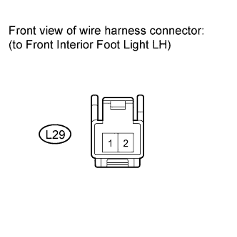
Disconnect the L29 front interior foot light LH connector.
-
Measure the voltage according to the value(s) in the table below.
Standard Voltage Tester Connection Condition Specified Condition L29-2 - Body ground Always 11 to 14 V
NG 
REPAIR OR REPLACE HARNESS OR CONNECTOR
OK 
-
-
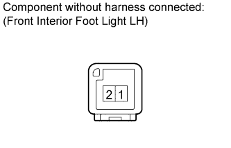
INSPECT NO. 1 INTERIOR ILLUMINATION LIGHT ASSEMBLY LH (FRONT INTERIOR FOOT LIGHT LH)
-
Remove the front interior foot light LH Click here.
-
Apply battery voltage to the front interior foot light and check the light condition.
OK Measurement Condition Specified Condition Battery positive (+) → Terminal 2
Battery negative (-) → Terminal 1
Interior illumination light comes on
NG
REPLACE NO. 1 INTERIOR ILLUMINATION LIGHT ASSEMBLY LH (FRONT INTERIOR FOOT LIGHT LH) Click here
OK
-
-
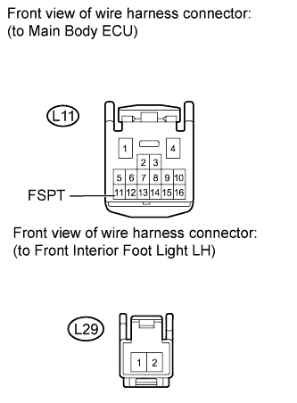
CHECK HARNESS AND CONNECTOR (MAIN BODY ECU - FRONT INTERIOR FOOT LIGHT LH)
-
Disconnect the L11 main body ECU connector.
-
Disconnect the L29 front interior foot light LH connector.
-
Measure the resistance according to the value(s) in the table below.
Standard Resistance Tester Connection Condition Specified Condition L11-11 (FSPT) - L29-1 Always Below 1 Ω L29-1 - Body ground Always 10 kΩ or higher
NG
REPAIR OR REPLACE HARNESS OR CONNECTOR
OK
-
-
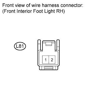
CHECK HARNESS AND CONNECTOR (FRONT INTERIOR FOOT LIGHT RH - BATTERY)
-
Disconnect the L81 front interior foot light RH connector.
-
Measure the voltage according to the value(s) in the table below.
Standard Voltage Tester Connection Condition Specified Condition L81-2 - Body ground Always 11 to 14 V
NG
REPAIR OR REPLACE HARNESS OR CONNECTOR
OK
-
-
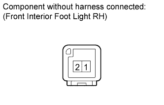
INSPECT NO. 1 INTERIOR ILLUMINATION LIGHT ASSEMBLY RH (FRONT INTERIOR FOOT RH)
-
Remove the front interior foot light RH Click here.
-
Apply battery voltage to the front interior foot light and check the light condition.
OK Measurement Condition Specified Condition Battery positive (+) → Terminal 2
Battery negative (-) → Terminal 1
Interior illumination light comes on
NG
REPLACE NO. 1 INTERIOR ILLUMINATION LIGHT ASSEMBLY RH (FRONT INTERIOR FOOT LIGHT RH) Click here
OK
-
-
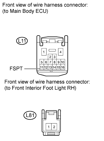
CHECK HARNESS AND CONNECTOR (MAIN BODY ECU - FRONT INTERIOR FOOT LIGHT RH)
-
Disconnect the L11 main body ECU connector.
-
Disconnect the L81 front interior foot light RH connector.
-
Measure the resistance according to the value(s) in the table below.
Standard Resistance Tester Connection Condition Specified Condition L11-11 (FSPT) - L81-1 Always Below 1 Ω L81-1 - Body ground Always 10 kΩ or higher
NG
REPAIR OR REPLACE HARNESS OR CONNECTOR
OK
-
-
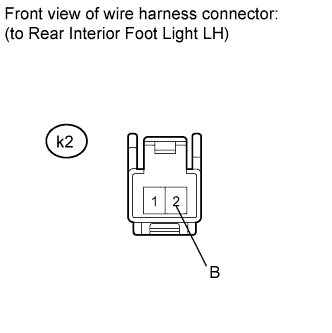
CHECK HARNESS AND CONNECTOR (REAR INTERIOR FOOT LIGHT LH - BATTERY)
-
Disconnect the k2 rear interior foot light LH connector.
-
Measure the voltage according to the value(s) in the table below.
Standard Voltage Tester Connection Condition Specified Condition k2-2 (B) - Body ground Always 11 to 14 V
NG
REPAIR OR REPLACE HARNESS OR CONNECTOR
OK
-
-
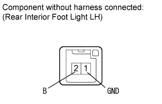
INSPECT INTERIOR ILLUMINATION LIGHT ASSEMBLY LH (REAR INTERIOR FOOT LIGHT LH)
-
Remove the rear interior foot light LH Click here.
-
Apply battery voltage to the rear interior foot light and check the light condition.
OK Measurement Condition Specified Condition Battery positive (+) → Terminal 2 (B)
Battery negative (-) → Terminal 1 (GND)
Interior illumination light comes on
NG
REPLACE INTERIOR ILLUMINATION LIGHT ASSEMBLY LH (REAR INTERIOR FOOT LIGHT LH) Click here
OK
-
-
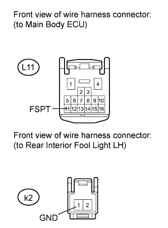
CHECK HARNESS AND CONNECTOR (MAIN BODY ECU - REAR INTERIOR ILLUMINATION LIGHT LH)
-
Disconnect the L11 main body ECU connector.
-
Disconnect the k2 rear interior illumination light LH connector.
-
Measure the resistance according to the value(s) in the table below.
Standard Resistance Tester Connection Condition Specified Condition L11-11 (FSPT) - k2-1 (GND) Always Below 1 Ω k2-1 (GND) - Body ground Always 10 kΩ or higher
NG
REPAIR OR REPLACE HARNESS OR CONNECTOR
OK
-
-
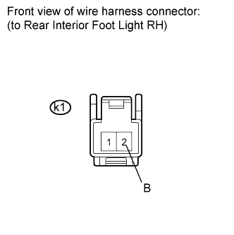
CHECK HARNESS AND CONNECTOR (REAR INTERIOR FOOT LIGHT RH - BATTERY)
-
Remove the k1 rear interior foot light RH connector.
-
Measure the voltage according to the value(s) in the table below.
Standard Voltage Tester Connection Condition Specified Condition k1-2 (B) - Body ground Always 11 to 14 V
NG
REPAIR OR REPLACE HARNESS OR CONNECTOR
OK
-
-
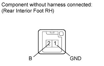
INSPECT NO. 1 INTERIOR ILLUMINATION LIGHT ASSEMBLY RH (REAR INTERIOR FOOT LIGHT RH)
-
Remove the rear interior foot light RH Click here.
-
Apply battery voltage to the rear interior foot light and check the light condition.
OK Measurement Condition Specified Condition Battery positive (+) → Terminal 2 (B)
Battery negative (-) → Terminal 1 (GND)
Interior illumination light comes on
NG
REPLACE INTERIOR ILLUMINATION LIGHT ASSEMBLY RH (REAR INTERIOR FOOT LIGHT RH) Click here
OK
-
-
CHECK HARNESS AND CONNECTOR (MAIN BODY ECU - REAR INTERIOR FOOT LIGHT RH)

-
Disconnect the L11 main body ECU connector.
-
Disconnect the k1 rear interior foot light RH connector.
-
Measure the resistance according to the value(s) in the table below.
Standard Resistance Tester Connection Condition Specified Condition L11-11 (FSPT) - k1-1 (GND) Always Below 1 Ω k1-1 (GND) - Body ground Always 10 kΩ or higher
NG
REPAIR OR REPLACE HARNESS OR CONNECTOR
OK
REPLACE MAIN BODY ECU (DRIVER SIDE JUNCTION BLOCK ASSEMBLY)
-