LIGHTING SYSTEM, Diagnostic DTC:B124E

| DTC Code | DTC Name |
|---|---|
| B124E | Flasher Relay Circuit |
DESCRIPTION
This DTC is stored when the main body ECU detects malfunctions in the turn signal flasher relay circuit.
| DTC Code | DTC Detection Condition | Trouble Area |
|---|---|---|
| B124E | Malfunction in turn signal flasher relay circuit |
|
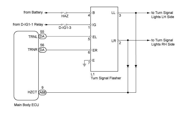
WIRING DIAGRAM
INSPECTION PROCEDURE
PROCEDURE
-
CLEAR DTC
-
Clear the DTCs Click here.
NEXT 
-
-
CHECK DTC
-
Operate the turn signal switch to cause the left and right turns signal lights to each blink for 3 seconds or more.
-
Check for DTCs Click here.
OK DTC B124E is not output.
NG 
PERFORM ACTIVE TEST USING GTS (TURN SIGNAL LIGHT) Click here
OK 
NORMAL
-
-
PERFORM ACTIVE TEST USING GTS (TURN SIGNAL LIGHT)
-
Using the GTS, perform the Active Test.
Tester Display Test Part Control Range Turn Light RH Relay Operation Turn signal light operation OFF - ON Turn Light LH Relay Operation Turn signal light operation OFF - ON OK Turn signal light condition is switched by Active Test.
NG
CHECK HARNESS AND CONNECTOR (TURN SIGNAL FLASHER - BATTERY AND BODY GROUND) Click here
OK
-
-
CHECK HARNESS AND CONNECTOR (MAIN BODY ECU - TURN SIGNAL FLASHER)
-
Disconnect the A68 ECU connector.
-
Disconnect the L1 flasher connector.
-
Disconnect the B1 or B11 headlight connector.
-
Disconnect the N10 or N1 front multiplex network door ECU connector.
-
Disconnect the S51 or S52 rear combination light connector.
-
Measure the resistance according to the value(s) in the table below.
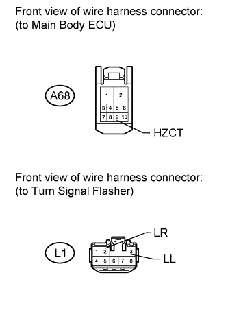
Standard resistance Tester Connection Condition Specified Condition A68-9 (HZCT) - L1-3 (LL) Always 1 MΩ or higher*1 Approximately 300 kΩ*2 A68-9 (HZCT) - L1-2 (LR) Always 1 MΩ or higher*1 Approximately 300 kΩ*2 A68-9 (HZCT) - Body ground Always 10 kΩ or higher Tech Tips
*1: Measure the resistance by connecting the positive (+) tester probe to terminal A68-9 (HZCT) and the negative (-) tester probe to terminal L1-3 (LL) or L1-2 (LR).
*2: Measure the resistance by connecting the positive (+) tester probe to terminal L1-3 (LL) or L1-2 (LR) and the negative (-) tester probe to terminal A68-9 (HZCT). Use this value only as a reference, as the resistance varies between several hundred and several hundred thousand ohms depending on the measurement instrument.
NG 
REPAIR OR REPLACE HARNESS OR CONNECTOR
OK
REPLACE MAIN BODY ECU
-
-
CHECK HARNESS AND CONNECTOR (TURN SIGNAL FLASHER - BATTERY AND BODY GROUND)
-
Disconnect the L1 flasher connector.
-
Measure the resistance according to the value(s) in the table below.
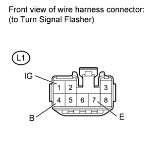
Standard resistance Tester Connection Condition Specified Condition L1-7 (E) - Body ground Always Below 1 Ω -
Measure the voltage according to the value(s) in the table below.
Standard voltage Tester Connection Switch Condition Specified Condition L1-4 (B) - Body ground Always 11 to 14 V L1-1 (IG) - Body ground Engine switch on (IG) 11 to 14 V
NG
REPAIR OR REPLACE HARNESS OR CONNECTOR
OK
-
-
CHECK HARNESS AND CONNECTOR (MAIN BODY ECU - TURN SIGNAL FLASHER)
-
Disconnect the A68 and DA ECU connectors.
-
Disconnect the L1 flasher connector.
-
Measure the resistance according to the value(s) in the table below.
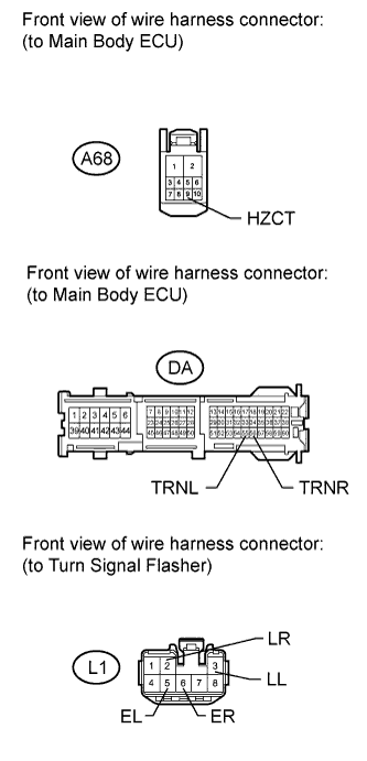
Standard resistance Tester Connection Condition Specified Condition A68-9 (HZCT) - L1-3 (LL) Always 1 MΩ or higher*1 Approximately 300 kΩ*2 A68-9 (HZCT) - L1-2 (LR) Always 1 MΩ or higher*1 Approximately 300 kΩ*2 DA-55 (TRNL) - L1-5 (EL) Always Below 1 Ω DA-56 (TRNR) - L1-6 (ER) Always Below 1 Ω DA-55 (TRNL) - Body ground Always 10 kΩ or higher DA-56 (TRNR) - Body ground Always 10 kΩ or higher Tech Tips
*1: Measure the resistance by connecting the positive (+) tester probe to terminal A68-9 (HZCT) and the negative (-) tester probe to terminal L1-3 (LL) or L1-2 (LR).
*2: Measure the resistance by connecting the positive (+) tester probe to terminal L1-3 (LL) or L1-2 (LR) and the negative (-) tester probe to terminal A68-9 (HZCT). Use this value only as a reference, as the resistance varies between several hundred and several hundred thousand ohms depending on the measurement instrument.
NG
REPAIR OR REPLACE HARNESS OR CONNECTOR
OK
-
-
CHECK TURN SIGNAL FLASHER ASSEMBLY (OPERATION)
-
Temporarily replace the turn signal flasher with a new or normally functioning one Click here.
-
Operate the turn signal switch to cause the left and right turns signal lights to each blink for 3 seconds or more.
-
Check for DTCs Click here.
OK DTC B124E is not output.
NG
REPLACE MAIN BODY ECU
OK
REPLACE TURN SIGNAL FLASHER ASSEMBLY Click here
-