LIGHTING SYSTEM, Diagnostic DTC:B2440, B2441

| DTC Code | DTC Name |
|---|---|
| B2440 | Lost Communication with AHS EDU LH Module |
| B2441 | Lost Communication with AHS EDU RH Module |
DESCRIPTION
This DTC is output when there is a malfunction in the LIN communication between the AFS ECU and headlight shade ECU.
| DTC Code | DTC Detection Condition | Trouble Area |
|---|---|---|
| B2440 | Headlight shade ECU LH communication error |
|
| B2441 | Headlight shade ECU RH communication error |
|
WIRING DIAGRAM
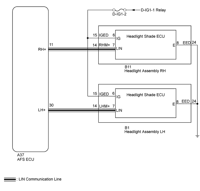
INSPECTION PROCEDURE
Note
Inspect the fuses for circuits related to this system before performing the following inspection procedure.
PROCEDURE
-
CLEAR DTC
-
Clear the DTC Click here.
NEXT 
-
-
CHECK FOR DTC
-
Turn the engine switch on (IG).
-
Check for DTC Click here.
OK DTC B2440 or B2441 output does not occur
NG 
CHECK HARNESS AND CONNECTOR (HEADLIGHT - BATTERY AND BODY GROUND) Click here
OK 
USE SIMULATION METHOD TO CHECK Click here
-
-
CHECK HARNESS AND CONNECTOR (HEADLIGHT - BATTERY AND BODY GROUND)
-
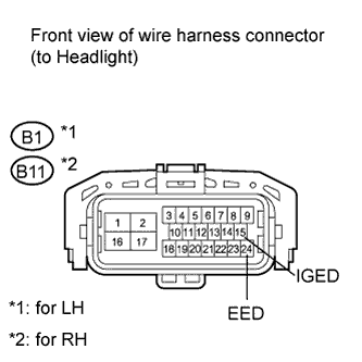
Disconnect the B1*1 or B11*2 headlight connector.
-
*1: for LH
-
*2: for RH
-
-
Measure the voltage according to the value(s) in the table below.
Standard Voltage for LH Tester Connection Condition Specified Condition B1-15 (IGED) - Body ground Always 11 to 14 V for RH Tester Connection Condition Specified Condition B11-15 (IGED) - Body ground Always 11 to 14 V -
Measure the resistance according to the value(s) in the table below.
Standard Resistance for LH Tester Connection Condition Specified Condition B1-24 (EED) - Body ground Always Below 1 Ω for RH Tester Connection Condition Specified Condition B11-24 (EED) - Body ground Always Below 1 Ω
NG 
REPAIR OR REPLACE HARNESS OR CONNECTOR
OK
-
-
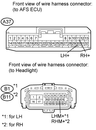
CHECK HARNESS AND CONNECTOR (AFS ECU - HEADLIGHT)
-
Disconnect the A37 AFS ECU connector.
-
Disconnect the B1*1 or B11*2 headlight connector.
-
*1: for LH
-
*2: for RH
-
-
Measure the resistance according to the value(s) in the table below.
Standard Resistance for LH Tester Connection Condition Specified Condition A37-30 (LH+) - B1-14 (LHM+) Always Below 1 Ω A37-30 (LH+) - Body ground Always 10 kΩ or higher for RH Tester Connection Condition Specified Condition A37-11 (RH+) - B11-14 (RHM+) Always Below 1 Ω A37-11 (RH+) - Body ground Always 10 kΩ or higher
NG
REPAIR OR REPLACE HARNESS OR CONNECTOR
OK
-
-
INSPECT HEADLIGHT ASSEMBLY
-
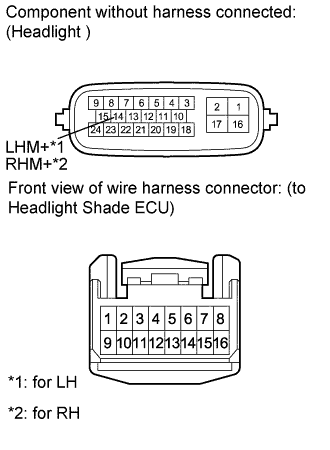
Remove the headlight Click here.
-
Disconnect the headlight shade ECU connector Click here.
-
Measure the resistance according to the value(s) in the table below.
Standard Resistance for LH Tester Connection Condition Specified Condition 14 (LHM+) - 7 (LIN) Always Below 1 Ω 15 (IGED) - 6 (IG) Always Below 1 Ω 24 (EED) - 8 (E) Always Below 1 Ω for RH Tester Connection Condition Specified Condition 14 (RHM+) - 7 (LIN) Always Below 1 Ω 15 (IGED) - 6 (IG) Always Below 1 Ω 24 (EED) - 8 (E) Always Below 1 Ω
NG
REPLACE HEADLIGHT ASSEMBLY Click here
OK
-
-
CHECK HEADLIGHT SHADE ECU
-
Temporarily replace the headlight shade ECU with a new or normally functioning one Click here.
-
Turn the engine switch on (IG).
-
Check for DTC Click here.
OK DTC B2440 or B2441 output does not occur
NG
REPLACE AFS ECU Click here
OK
END (HEADLIGHT SHADE ECU WAS DEFECTIVE)
-