DRIVING SUPPORT ECU INSTALLATION

Tech Tips
A bolt without a torque specification is shown in the standard bolt chart Click here.
-
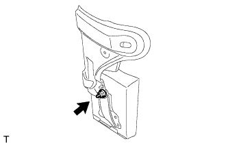
INSTALL DRIVING SUPPORT ECU ASSEMBLY
-
Install the driving support ECU assembly with the nut.
Note
-
Do not use a driving support ECU assembly which has been dropped or subjected to any strong shocks.
-
During the removal and installation, do not remove the drip-proof cover.
-
When a new driving support ECU assembly is installed, perform initialization.
-
-
-
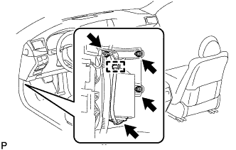
INSTALL DASH PANEL EXTENSION LH
-
Connect the connector.
-
Install the dash panel extension LH and driving support ECU assembly as a unit with the 2 nuts and bolt.
-
Attach the wire harness clamp.
-
for RHD:
Return the floor carpet to its original position.
-
-
INSTALL NO. 3 DASH PANEL INSULATOR PAD (for LHD)
-
Install the No. 3 dash panel insulator pad.
-
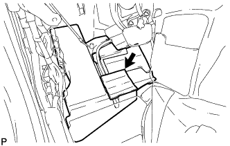
Connect the No. 2 cooler unit drain hose.
-
Clean the No. 3 dash panel insulator pad surface.
-
Attach a new No. 1 cooling unit packing in the position shown in the illustration.
-
Return the floor carpet to its original position.
-
Attach the clamp.
-
-
INSTALL ACCELERATOR PEDAL SENSOR ASSEMBLY (for LHD)
Note
-
This accelerator pedal does not require lubrication.
Do not apply oil or other lubrication to the accelerator pedal sensor assembly.
If applied, the accelerator pedal sensor assembly must be replaced.
-
Avoid physical shocks to the accelerator pedal sensor assembly.
-
Do not disassemble the accelerator pedal sensor assembly.
-
Connect the tip of the accelerator pedal sensor assembly to the bracket.
-
Install the accelerator pedal sensor assembly with the 3 nuts.
- Torque:
- 5.4 N*m { 55 kgf*cm, 48 in.*lbf }
-
Connect the accelerator pedal sensor assembly connector.
-
-
INSTALL COWL SIDE TRIM BOARD LH
-
Attach the 3 claws to install the cowl side trim board LH.
-
-
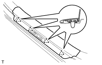
INSTALL FRONT DOOR SCUFF PLATE LH
-
Attach the 4 clips.
-
Attach the 7 claws to install the front door scuff plate LH.
-
-
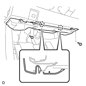
INSTALL NO. 1 INSTRUMENT PANEL UNDER COVER SUB-ASSEMBLY (for LHD)
-
Connect each connector and each wire harness clamp.
-
Attach the 2 claws to connect the DLC3.
-
Attach the 2 claws to install the No. 1 instrument panel under cover sub-assembly.
-
Install the 2 screws.
-
-
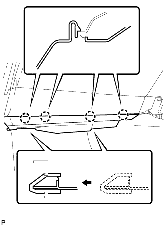
INSTALL NO. 2 INSTRUMENT PANEL UNDER COVER SUB-ASSEMBLY (for RHD)
-
Connect the connector.
-
Insert the 2 guides.
-
Attach the 4 claws to install the No. 2 instrument panel under cover sub-assembly.
-