LIGHTING SYSTEM, Diagnostic DTC:B1244

| DTC Code | DTC Name |
|---|---|
| B1244 | Light Sensor Circuit Malfunction |
DESCRIPTION
This DTC is output when a failure of the automatic light control sensor circuit is detected.
| DTC Code | DTC Detection Condition | Trouble Area |
|---|---|---|
| B1244 | When either condition below is met:
|
|
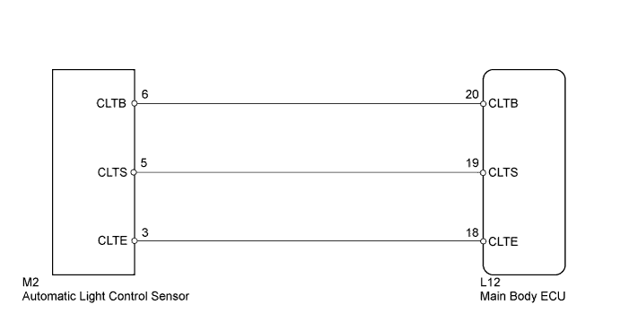
WIRING DIAGRAM
INSPECTION PROCEDURE
PROCEDURE
-
CLEAR DTC
-
Clear the DTC Click here.
NEXT 
-
-
CHECK DTC
-
Check for DTC Click here.
OK DTC B1244 output does not occur.
NG 
READ VALUE USING GTS (AUTOMATIC LIGHT CONTROL SENSOR) Click here
OK 
NORMAL
-
-
READ VALUE USING GTS (AUTOMATIC LIGHT CONTROL SENSOR)
-
Using the GTS, read the Data List.
Main Body Tester Display Measurement Item/Range Normal Condition Diagnostic Note Illumination rate information Condition of automatic light control sensor/0 to 2162.65 ms Condition value will be displayed - OK Output illuminance is as shown in table above.
NG
CHECK MAIN BODY ECU (CLTB - CLTE VOLTAGE) Click here
OK
REPLACE MAIN BODY ECU
-
-
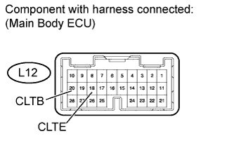
CHECK MAIN BODY ECU (CLTB - CLTE VOLTAGE)
-
Measure the voltage according to the value(s) in the table below.
Standard voltage Tester Connection Switch Condition Specified Condition L12-20 (CLTB) - L12-18 (CLTE) Engine switch on (IG) 11 to 14 V
NG 
REPLACE MAIN BODY ECU
OK
-
-
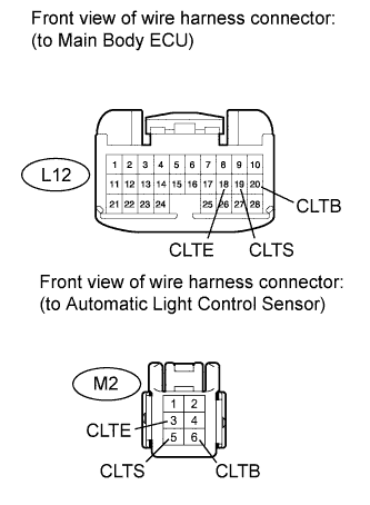
CHECK HARNESS AND CONNECTOR (MAIN BODY ECU - AUTOMATIC LIGHT CONTROL SENSOR)
-
Disconnect the L12 ECU connector.
-
Disconnect the M2 sensor connector.
-
Measure the resistance according to the value(s) in the table below.
Standard resistance Tester Connection Condition Specified Condition L12-20 (CLTB) - M2-6 (CLTB) Always Below 1 Ω L12-19 (CLTS) - M2-5 (CLTS) L12-18 (CLTE) - M2-3 (CLTE) L12-20 (CLTB) - Body ground Always 10 kΩ or higher L12-19 (CLTS) - Body ground L12-18 (CLTE) - Body ground
NG
REPAIR OR REPLACE HARNESS OR CONNECTOR
OK
REPLACE AUTOMATIC LIGHT CONTROL SENSOR Click here
-