CAN COMMUNICATION SYSTEM (for RHD), Diagnostic DTC:U1111

| DTC Code | DTC Name |
|---|---|
| U1111 | Lost Communication with Body No. 5 Module |
DESCRIPTION
| DTC Code | DTC Detection Condition | Trouble Area |
|---|---|---|
| U1111 | There is no communication from the front multiplex network light ECU (front controller). |
|
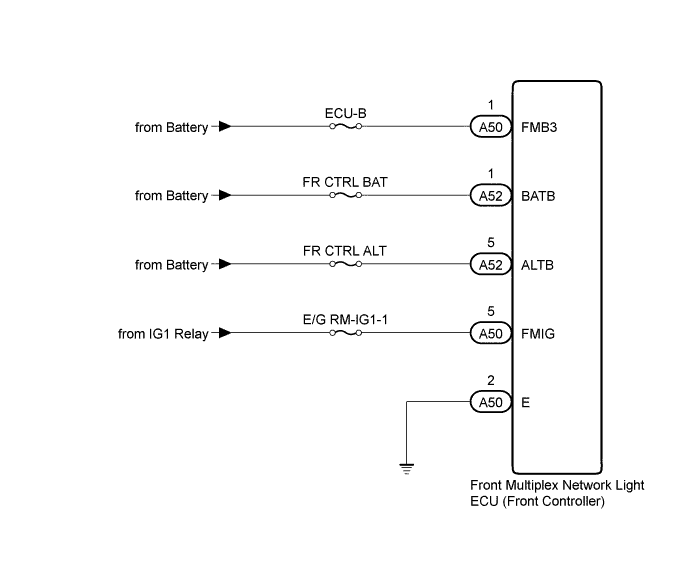
WIRING DIAGRAM
INSPECTION PROCEDURE
Note
Inspect the fuses for circuits related to this system before performing the following inspection procedure.
PROCEDURE
-
CHECK HARNESS AND CONNECTOR (FRONT CONTROLLER - BATTERY AND BODY GROUND)
-
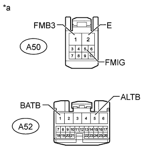
Text in Illustration *a Front view of wire harness connector
(to Front Multiplex Network Light ECU [Front Controller])
Disconnect the front multiplex network light ECU (front controller) connectors.
-
Measure the voltage according to the value(s) in the table below.
Standard Voltage Tester Connection Condition Specified Condition A50-1 (FMB3) - Body ground Always 11 to 14 V A52-1 (BATB) - Body ground Always 11 to 14 V A52-5 (ALTB) - Body ground Always 11 to 14 V A50-5 (FMIG) - Body ground Engine switch on (IG) 11 to 14 V -
Measure the resistance according to the value(s) in the table below.
Standard Resistance Tester Connection Condition Specified Condition A50-2 (E) - Body ground Always Below 1 Ω
NG 
REPAIR OR REPLACE HARNESS OR CONNECTOR
OK 
REPLACE FRONT MULTIPLEX NETWORK LIGHT ECU (FRONT CONTROLLER)
-