PRE-CRASH SAFETY SYSTEM, Diagnostic DTC:C1A6A

| DTC Code | DTC Name |
|---|---|
| C1A6A | Infrared Signal Circuit |
DESCRIPTION
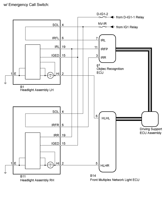
w/ Emergency Call Switch:If a headlight assembly illumination malfunction or automatic light sensor signal malfunction is detected, or the near infrared light signal input from the headlight assembly indicates an open circuit, a signal is sent to the driving support ECU and DTC C1A6A is output.
| DTC Code | DTC Detection Condition | Trouble Area |
|---|---|---|
| C1A6A | When one of the following conditions is met while the engine switch is on (IG):
|
|
Note
After replacing the object recognition ECU, if the headlight assembly is not connected when the engine switch is turned on (IG), the ECU records the wrong headlight type and outputs DTC C1A6A.
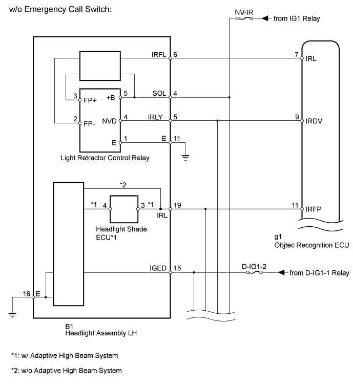
If a headlight assembly illumination malfunction or automatic light sensor signal malfunction is detected, or the near infrared ray filter position signal or low beam signal input from the headlight assembly indicates an open circuit, a signal is sent to the driving support ECU and DTC C1A6A is output.
| DTC Code | DTC Detection Condition | Trouble Area |
|---|---|---|
| C1A6A | When one of the following conditions is met while the engine switch is on (IG):
|
|
-
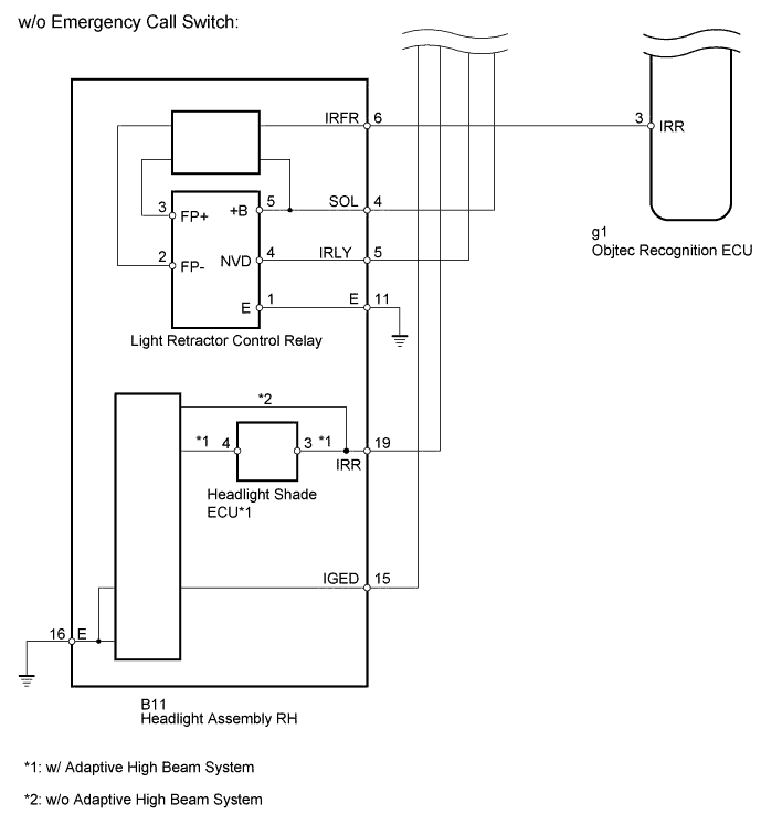
*: w/ Adaptive High Beam System
WIRING DIAGRAM
INSPECTION PROCEDURE
Note
Inspect the fuses and bulbs for circuits related to this system before performing the following inspection procedure.
PROCEDURE
-
CHECK LIGHTING SYSTEM
-
Check if the lighting system is malfunctioning Click here.
OK No malfunctions are present in the lighting system.
NG 
GO TO LIGHTING SYSTEM Click here
OK 
-
-
CHECK CAN COMMUNICATION SYSTEM
-
Use the Techstream to check if the CAN communication system is functioning normally Click here.
Result Result Proceed to CAN communication DTCs are not output. A CAN communication DTCs are output (for LHD). B CAN communication DTCs are output (for RHD). C
B
GO TO CAN COMMUNICATION SYSTEM Click here
C
GO TO CAN COMMUNICATION SYSTEM Click here
A
-
-
CHECK VEHICLE TYPE
-
Check vehicle type.
Result Result Proceed to w/ Emergency Call Switch A w/o Emergency Call Switch B
B 
CHECK OBJECT RECOGNITION ECU Click here
A
-
-
PERFORM ACTIVE TEST USING INTELLIGENT TESTER
-
Select the Active Test, use the intelligent tester to generate a control command, and then check that the near infrared ray emitter operates Click here.
Pre-Crash 2 Tester Display Test Part Control Range Diagnostic Note Infrared Signal Status Near infrared ray emitter operates ON/OFF - OK A blurred light is emitted.
NG
CHECK HARNESS AND CONNECTOR (HEADLIGHT ASSEMBLY - FRONT MULTIPLEX NETWORK LIGHT ECU AND BODY GROUND) Click here
OK
-
-
CHECK OBJECT RECOGNITION ECU
-
Using the Techstream, enter the following menus: Body / Pre-Crash 2 / Active Test.
-
Select "Infrared Signal Status", and perform the Active Test.
-
Measure the voltage according to the value(s) in the table below.
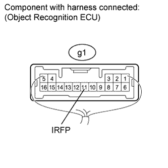
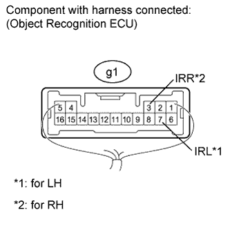
Standard voltage Tester Connection Condition Specified Condition g1-11 (IRFP) - Body ground
-
Engine switch on (IG)
-
Active Test is performed
Battery voltage x 0.3 to Battery voltage x 0.6 V -
NG
CHECK HARNESS AND CONNECTOR (HEADLIGHT ASSEMBLY - BATTERY AND BODY GROUND) Click here
OK
-
-
CHECK OBJECT RECOGNITION ECU
-
Measure the voltage according to the value(s) in the table below.
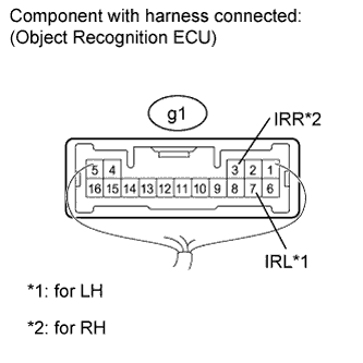
Standard voltage for LH Tester Connection Switch Condition Specified Condition g1-7 (IRL) - Body ground Engine switch on (IG) 11 to 14 V for RH Tester Connection Switch Condition Specified Condition g1-3 (IRR) - Body ground Engine switch on (IG) 11 to 14 V
NG
CHECK HARNESS AND CONNECTOR (HEADLIGHT ASSEMBLY - OBJECT RECOGNITION ECU AND BATTERY) Click here
OK 
REPLACE OBJECT RECOGNITION ECU Click here
-
-
CHECK HARNESS AND CONNECTOR (HEADLIGHT ASSEMBLY - OBJECT RECOGNITION ECU AND BATTERY)
-
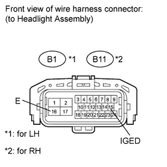
Disconnect the B1*1 and/or B11*2 headlight connector.
-
*1: for LH
-
*2: for RH
-
-
Disconnect the g1 ECU connector.
-
Measure the voltage according to the value(s) in the table below.
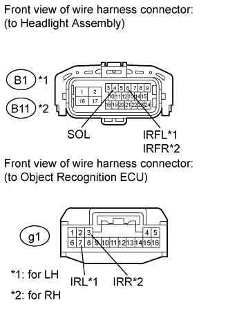
Standard voltage for LH Tester Connection Switch Condition Specified Condition B1-4 (SOL) - Body ground Engine switch on (IG) 11 to 14 V for RH Tester Connection Switch Condition Specified Condition B11-4 (SOL) - Body ground Engine switch on (IG) 11 to 14 V -
Measure the resistance according to the value(s) in the table below.
Standard resistance for LH Tester Connection Condition Specified Condition B1-6 (IRFL) - g1-7 (IRL) Always Below 1 Ω B1-6 (IRFL) or g1-7 (IRL) - Body ground Always 10 kΩ or higher for RH Tester Connection Condition Specified Condition B11-6 (IRFR) - g1-3 (IRR) Always Below 1 Ω B11-6 (IRFR) or g1-3 (IRR) - Body ground Always 10 kΩ or higher Result Result Proceed to OK (for LH) A OK (for RH) B NG C
B
REPLACE HEADLIGHT UNIT RH Click here
C
REPAIR OR REPLACE HARNESS OR CONNECTOR
A
REPLACE HEADLIGHT UNIT LH Click here
-
-
CHECK HARNESS AND CONNECTOR (HEADLIGHT ASSEMBLY - BATTERY AND BODY GROUND)
-
Disconnect the B1*1 and/or B11*2 headlight connector.
-
*1: for LH
-
*2: for RH
-
-
Measure the voltage according to the value(s) in the table below.
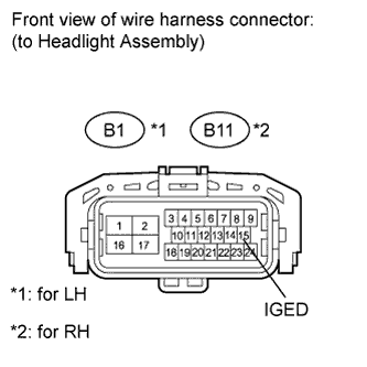
Standard voltage for LH Tester Connection Switch Condition Specified Condition B1-15 (IGED) - Body ground Engine switch on (IG) 11 to 14 V for RH Tester Connection Switch Condition Specified Condition B11-15 (IGED) - Body ground Engine switch on (IG) 11 to 14 V
NG
REPAIR OR REPLACE HARNESS OR CONNECTOR
OK
-
-
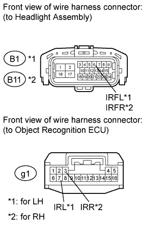
CHECK HARNESS AND CONNECTOR (HEADLIGHT ASSEMBLY - OBJECT RECOGNITION ECU)
-
Disconnect the B1*1 and/or B11*2 headlight connector.
-
*1: for LH
-
*2: for RH
-
-
Disconnect the g1 ECU connector.
-
Measure the resistance according to the value(s) in the table below.
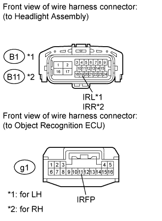
Standard resistance for LH Tester Connection Condition Specified Condition B1-19 (IRL) - g1-11 (IRFP) Always Below 1 Ω B1-19 (IRL) or g1-11 (IRFP) - Body ground Always 10 kΩ or higher for RH Tester Connection Condition Specified Condition B11-19 (IRR) - g1-11 (IRFP) Always Below 1 Ω B11-19 (IRR) or g1-11 (IRFP) - Body ground Always 10 kΩ or higher Result Result Proceed to OK (for LH) A OK (for RH) B NG C
B
REPLACE HEADLIGHT UNIT RH Click here
C
REPAIR OR REPLACE HARNESS OR CONNECTOR
A
REPLACE HEADLIGHT UNIT LH Click here
-
-
CHECK HARNESS AND CONNECTOR (HEADLIGHT ASSEMBLY - FRONT MULTIPLEX NETWORK LIGHT ECU AND BODY GROUND)
-
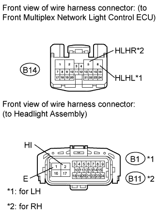
Disconnect the B1*1 and/or B11*2 headlight connector.
-
*1: for LH
-
*2: for RH
-
-
Disconnect the B14 ECU connector.
-
Measure the resistance according to the value(s) in the table below.
Standard resistance for LH Tester Connection Condition Specified Condition B1-2 (HI) - B14-6 (HLHL) Always Below 1 Ω B1-1 (E) - Body ground Always Below 1 Ω B1-2 (HI) or B14-6 (HLHL) - Body ground Always 10 kΩ or higher for RH Tester Connection Condition Specified Condition B11-2 (HI) - B14-5 (HLHR) Always Below 1 Ω B11-1 (E) - Body ground Always Below 1 Ω B11-2 (HI) or B14-5 (HLHR) - Body ground Always 10 kΩ or higher
NG
REPAIR OR REPLACE HARNESS OR CONNECTOR
OK
-
-
CHECK FRONT MULTIPLEX NETWORK LIGHT ECU
-
Temporarily replace the front multiplex network light ECU with a new or normally functioning one.
-
Enter the following menus: Body / Pre-Crash 2 / DTC Click here.
-
Select "Clear" and clear the data.
-
Recheck for DTC Click here.
Result Result Proceed to DTC C1A6A is not output A DTC C1A6A is output (for LH) B DTC C1A6A is output (for RH) C
B
REPLACE HEADLIGHT UNIT LH Click here
C
REPLACE HEADLIGHT UNIT RH Click here
A
END (FRONT MULTIPLEX NETWORK LIGHT ECU IS DEFECTIVE)
-
-
CHECK OBJECT RECOGNITION ECU
-
Measure the voltage according to the value(s) in the table below.
Standard voltage for LH Tester Connection Condition Specified Condition g1-7 (IRL) - Body ground Vehicle stopped Below 1 V for RH Tester Connection Condition Specified Condition g1-3 (IRR) - Body ground Vehicle stopped Below 1 V
NG
CHECK HARNESS AND CONNECTOR (HEADLIGHT ASSEMBLY - OBJECT RECOGNITION ECU) Click here
OK
-
-
PERFORM ACTIVE TEST USING INTELLIGENT TESTER
-
Select the Active Test, use the intelligent tester to generate a control command, and then check that the near infrared ray emitter operates Click here.
Pre-Crash 2 Tester Display Test Part Control Range Diagnostic Note Infrared Signal Status Near infrared ray emitter operates ON/OFF - OK A blurred light is emitted.
NG
CHECK HARNESS AND CONNECTOR (HEADLIGHT ASSEMBLY - OBJECT RECOGNITION ECU) Click here
OK
-
-
CHECK OBJECT RECOGNITION ECU
-
Using the Techstream, enter the following menus: Body / Pre-Crash 2 / Active Test.
-
Select "Infrared Signal Status", and perform the Active Test.
-
Measure the voltage according to the value(s) in the table below.
Standard voltage Tester Connection Condition Specified Condition g1-11 (IRFP) - Body ground
-
Engine switch on (IG)
-
Active Test is performed
Battery voltage x 0.3 to Battery voltage x 0.6 V -
NG
CHECK HARNESS AND CONNECTOR (HEADLIGHT ASSEMBLY - BATTERY AND BODY GROUND) Click here
OK
REPLACE OBJECT RECOGNITION ECU Click here
-
-
CHECK HARNESS AND CONNECTOR (HEADLIGHT ASSEMBLY - OBJECT RECOGNITION ECU)
-
Disconnect the B1*1 and/or B11*2 headlight connector.
-
*1: for LH
-
*2: for RH
-
-
Disconnect the g1 ECU connector.
-
Measure the resistance according to the value(s) in the table below.
Standard resistance for LH Tester Connection Condition Specified Condition B1-6 (IRFL) - g1-7 (IRL) Always Below 1 Ω B1-6 (IRFL) or g1-7 (IRL) - Body ground Always 10 kΩ or higher for RH Tester Connection Condition Specified Condition B11-6 (IRFR) - g1-3 (IRR) Always Below 1 Ω B11-6 (IRFR) or g1-3 (IRR) - Body ground Always 10 kΩ or higher
NG
REPAIR OR REPLACE HARNESS OR CONNECTOR
OK
-
-
CHECK OBJECT RECOGNITION ECU
-
Check the waveform of the television camera assembly using an oscilloscope.
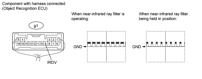
Item Item Content Terminal No. (Symbol) g1-9 (IRDV) - Body ground Tool Setting 5 V/DIV., 10 ms/DIV. Condition Vehicle stopped OK Waveform is as shown in the illustration. Result Result Proceed to OK A NG (for LH) B NG (for RH) C
B
REPLACE HEADLIGHT UNIT LH Click here
C
REPLACE HEADLIGHT UNIT RH Click here
A
REPLACE OBJECT RECOGNITION ECU Click here
-
-
CHECK HARNESS AND CONNECTOR (HEADLIGHT ASSEMBLY - BATTERY AND BODY GROUND)
-
Disconnect the B1*1 and/or B11*2 headlight connector.
-
*1: for LH
-
*2: for RH
-
-
Measure the voltage according to the value(s) in the table below.
Standard voltage for LH Tester Connection Switch Condition Specified Condition B1-15 (IGED) - Body ground Engine switch on (IG) 11 to 14 V for RH Tester Connection Switch Condition Specified Condition B11-15 (IGED) - Body ground Engine switch on (IG) 11 to 14 V -
Measure the resistance according to the value(s) in the table below.
Standard resistance for LH Tester Connection Condition Specified Condition B1-16 (E) - Body ground Always Below 1 Ω for RH Tester Connection Condition Specified Condition B11-16 (E) - Body ground Always Below 1 Ω
NG
REPAIR OR REPLACE HARNESS OR CONNECTOR
OK
-
-
CHECK HARNESS AND CONNECTOR (HEADLIGHT ASSEMBLY - OBJECT RECOGNITION ECU)
-
Disconnect the B1*1 and/or B11*2 headlight connector.
-
*1: for LH
-
*2: for RH
-
-
Disconnect the g1 ECU connector.
-
Measure the resistance according to the value(s) in the table below.
Standard resistance for LH Tester Connection Condition Specified Condition B1-19 (IRL) - g1-11 (IRFP) Always Below 1 Ω B1-19 (IRL) or g1-11 (IRFP) - Body ground Always 10 kΩ or higher for RH Tester Connection Condition Specified Condition B11-19 (IRR) - g1-11 (IRFP) Always Below 1 Ω B11-19 (IRR) or g1-11 (IRFP) - Body ground Always 10 kΩ or higher Result Result Proceed to OK (w/ Adaptive High Beam System) A OK (for LH [w/o Adaptive High Beam System]) B OK (for RH [w/o Adaptive High Beam System]) C NG D
B
REPLACE HEADLIGHT UNIT LH Click here
C
REPLACE HEADLIGHT UNIT RH Click here
D
REPAIR OR REPLACE HARNESS OR CONNECTOR
A
-
-
CHECK HEADLIGHT SHADE ECU
-
Temporarily replace the headlight shade ECU with a new or normally functioning one.
-
Enter the following menus: Body / Pre-Crash 2 / DTC Click here.
-
Select "Clear" and clear the data.
-
Recheck for DTC Click here.
Result Result Proceed to DTC C1A6A is not output A DTC C1A6A is output (for LH) B DTC C1A6A is output (for RH) C
B
REPLACE HEADLIGHT UNIT LH Click here
C
REPLACE HEADLIGHT UNIT RH Click here
A
END (HEADLIGHT SHADE ECU IS DEFECTIVE)
-
-
CHECK HARNESS AND CONNECTOR (HEADLIGHT ASSEMBLY - OBJECT RECOGNITION ECU)
-
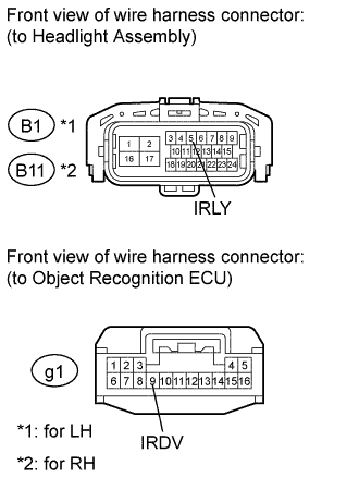
Disconnect the B1*1 and/or B11*2 headlight connector.
-
*1: for LH
-
*2: for RH
-
-
Disconnect the g1 ECU connector.
-
Measure the resistance according to the value(s) in the table below.
Standard resistance for LH Tester Connection Condition Specified Condition B1-5 (IRLY) - g1-9 (IRDV) Always Below 1 Ω B1-5 (IRLY) or g1-9 (IRDV) - Body ground Always 10 kΩ or higher for RH Tester Connection Condition Specified Condition B11-5 (IRLY) - g1-9 (IRDV) Always Below 1 Ω B11-5 (IRLY) or g1-9 (IRDV) - Body ground Always 10 kΩ or higher
NG
REPAIR OR REPLACE HARNESS OR CONNECTOR
OK
-
-
CHECK HARNESS AND CONNECTOR (HEADLIGHT ASSEMBLY - BATTERY AND BODY GROUND)
-
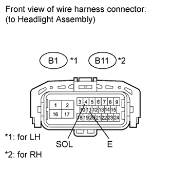
Disconnect the B1*1 and/or B11*2 headlight connector.
-
*1: for LH
-
*2: for RH
-
-
Measure the voltage according to the value(s) in the table below.
Standard voltage for LH Tester Connection Switch Condition Specified Condition B1-4 (SOL) - Body ground Engine switch on (IG) 11 to 14 V for RH Tester Connection Switch Condition Specified Condition B11-4 (SOL) - Body ground Engine switch on (IG) 11 to 14 V -
Measure the resistance according to the value(s) in the table below.
Standard resistance for LH Tester Connection Condition Specified Condition B1-11 (E) - Body ground Always Below 1 Ω for RH Tester Connection Condition Specified Condition B11-11 (E) - Body ground Always Below 1 Ω
NG
REPAIR OR REPLACE HARNESS OR CONNECTOR
OK
-
-
CHECK LIGHT RETRACTOR CONTROL RELAY
-
Temporarily replace the light retractor control relay with a new or normally functioning one.
-
Enter the following menus: Body / Pre-Crash 2 / DTC Click here.
-
Select "Clear" and clear the data.
-
Recheck for DTC Click here.
OK DTC C1A6A is not output.
NG
CHECK OBJECT RECOGNITION ECU Click here
OK
END (LIGHT RETRACTOR CONTROL RELAY IS DEFECTIVE)
-
-
CHECK OBJECT RECOGNITION ECU
-
Temporarily replace the headlight shade ECU with a new or normally functioning one.
-
Enter the following menus: Body / Pre-Crash 2 / DTC Click here.
-
Select "Clear" and clear the data.
-
Recheck for DTC Click here.
Result Result Proceed to DTC C1A6A is not output A DTC C1A6A is output (for LH) B DTC C1A6A is output (for RH) C
B
REPLACE HEADLIGHT UNIT LH Click here
C
REPLACE HEADLIGHT UNIT RH Click here
A
END (OBJECT RECOGNITION ECU IS DEFECTIVE)
-