DRIVER MONITOR ECU (for LHD) INSTALLATION

Tech Tips
A bolt without a torque specification is shown in the standard bolt chart Click here.
-
INSTALL DRIVER MONITOR ECU ASSEMBLY
-
Install the driver monitor ECU assembly with the nut.
-
Install the ECU unit with the 2 nuts.
- Torque:
- 8.5 N*m { 86 kgf*cm, 75 in.*lbf }
-
Connect the 3 connectors.
-
-
INSTALL DRIVER SIDE KNEE AIRBAG ASSEMBLY
-
Check that the engine switch is off.
-
Check that the cable is disconnected from the negative (-) battery terminal.
CAUTION:
Wait at least 90 seconds after disconnecting the cable from the negative (-) battery terminal to disable the SRS system.
-
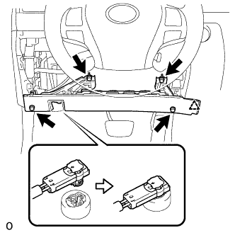
Connect the airbag connector.
Note
When connecting airbag connector, take care not to damage the airbag wire harness.
-
Push in the lock to connect the airbag connector.
-
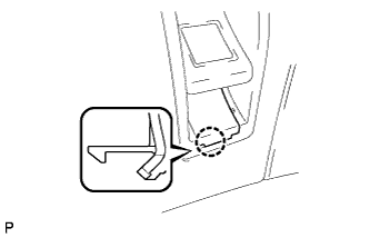
Attach the claw to connect the hood lock control lever sub-assembly to the driver side knee airbag assembly.
-
Attach the clip to install the driver side knee airbag assembly.
-
Install the 4 bolts.
- Torque:
- 10 N*m { 102 kgf*cm, 7 ft.*lbf }
Note
Confirm that the driver side knee airbag assembly is installed securely without any excessive gaps and is not protruding outward.
-
-
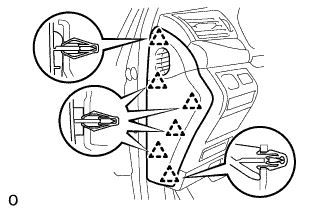
INSTALL NO. 1 INSTRUMENT PANEL SAFETY PAD SUB-ASSEMBLY
-
Connect each connector.
-
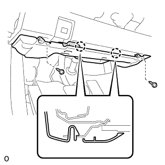
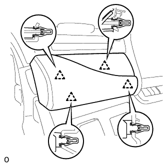
Attach the 5 clips and claw to install the No. 1 instrument panel safety pad sub-assembly.
-
Install the screw <C> and bolt.
-
Attach the claw to install the switch base hole cover to the No. 1 instrument panel safety pad sub-assembly.
-
-
INSTALL NO. 1 INSTRUMENT PANEL UNDER COVER SUB-ASSEMBLY
-
Connect each connector and each wire harness clamp.
-
Attach the 2 claws to connect the DLC3.
-
Attach the 2 claws to install the No. 1 instrument panel under cover sub-assembly.
-
Install the 2 screws.
-
-
INSTALL INSTRUMENT PANEL ORNAMENT
-
Connect the connector.
-
Attach the 4 clips to install the instrument panel ornament.
-
-
INSTALL INSTRUMENT SIDE PANEL LH
-
Attach the 6 clips to install the instrument side panel LH.
-
-
CONNECT CABLE TO NEGATIVE BATTERY TERMINAL
Note
When disconnecting the cable, some systems need to be initialized after the cable is reconnected Click here.
-
INSTALL COWL TOP VENTILATOR LOUVER RH
-

for LHD:
Install the 6 clips and cowl top ventilator louver RH.
Note
If the cowl top ventilator louver RH is not properly installed, water may leak into the engine room and cause malfunctions. Therefore, make sure the cowl top ventilator louver RH is installed properly.
-

for RHD:
Install the 6 clips and cowl top ventilator louver LH.
Note
If the cowl top ventilator louver LH is not properly installed, water may leak into the engine room and cause malfunctions. Therefore, make sure the cowl top ventilator louver LH is installed properly.
-
-
CHECK SRS WARNING LIGHT